Jessica Rocchiccioli
I am a Italian high school student in Erasmus on Bordeaux for one month.
MY STUDIES
I frequent the last year of a technical institute for Mechanics and Mechatronics "ITT F. Vecchiacchi"
I can use 3D CAD, CAM, design programs and I am able to work with industrial machinery like 3D printer, CNC lathe and milling machine.
FIRST DAY IN FABLAB
On my first day at FabLab Cohabit, I designed a small object using FreeCAD and printed it to test the printers. 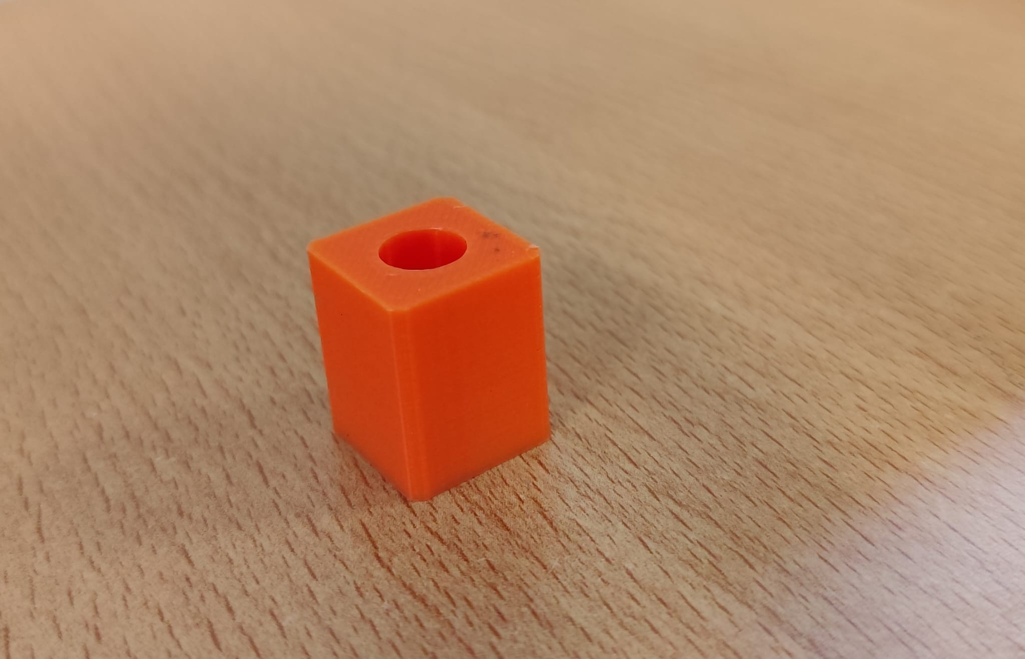 Link to the file : dado.FCStd
Afterwards, I also created a keychain to be cut and engraved using the laser cutter." 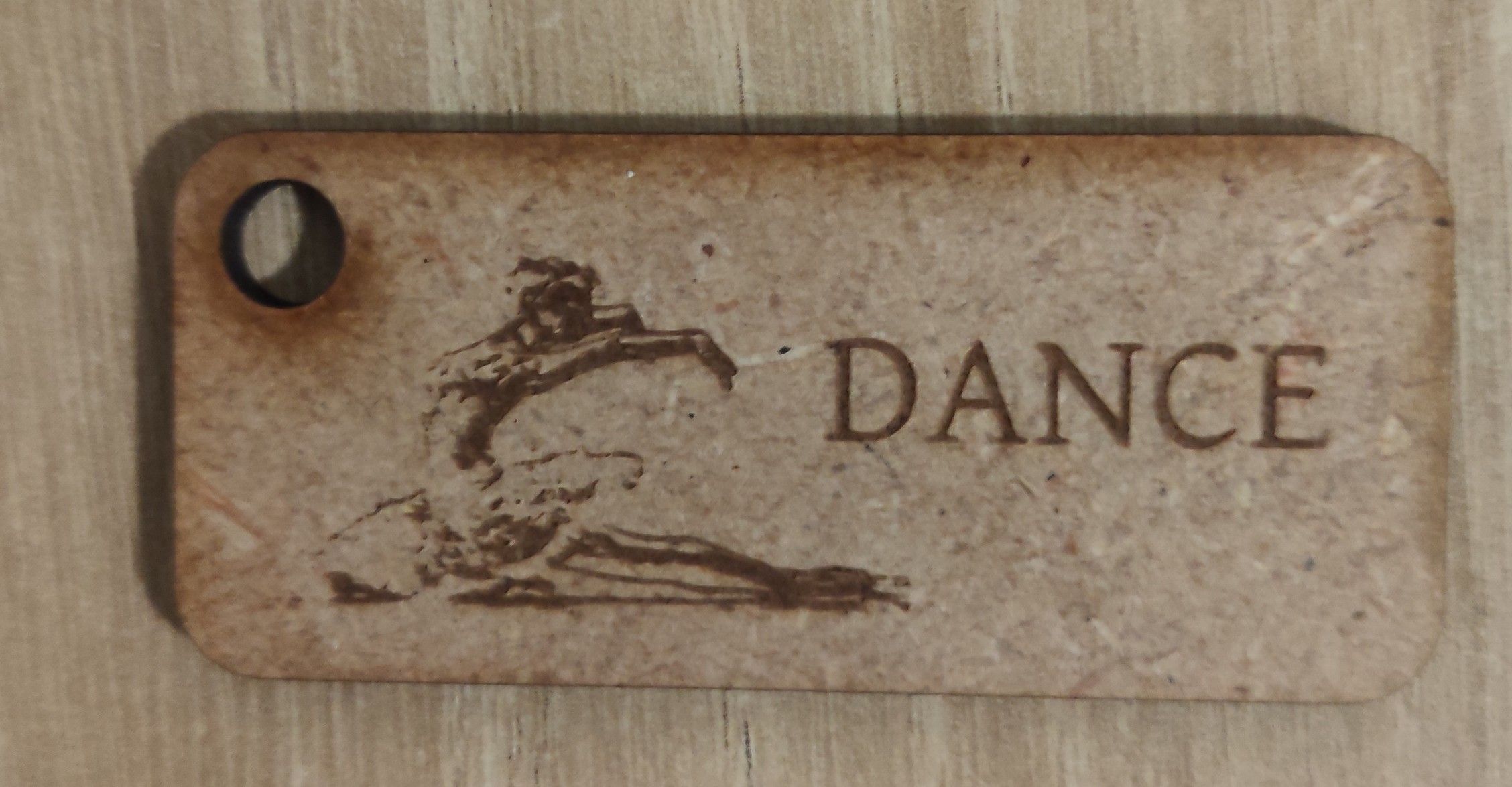 Link to the file : dance.svg
FASTENERS FOR PANELS
I created a locking mechanism for the panels of the 'INCLUENDO' project, an escape game themed around invisible disabilities.
1. CONTEXT AND OBJECTIVE
During the collaboration at Fab Lab Coh@bit, Pierre Grange Praderas asked to redesign the panel locking systems for the "INCLUEDO" project, an escape room centered on the theme of invisible disabilities. This intervention became necessary as previously tested solutions failed to ensure proper operation.
2. PRELIMINARY ANALYSIS AND DIMENSIONAL SURVEY
The work began with an on-site analysis to check panel layout, attachment methods, and the reasons behind the failure of previous attempts. Subsequently, using a caliper, the necessary dimensions were measured and a manual sketch was drawn to define the interlocking principle.
3. PROTOTYPE DEVELOPMENT
The entire prototyping process took place over 3 days. The 3D modeling was carried out using FreeCAD software, and the parts were manufactured using PLA 3D printing:
1st Prototype : Created to evaluate the overall fit, tolerances, and the mating of the upper section with the profile.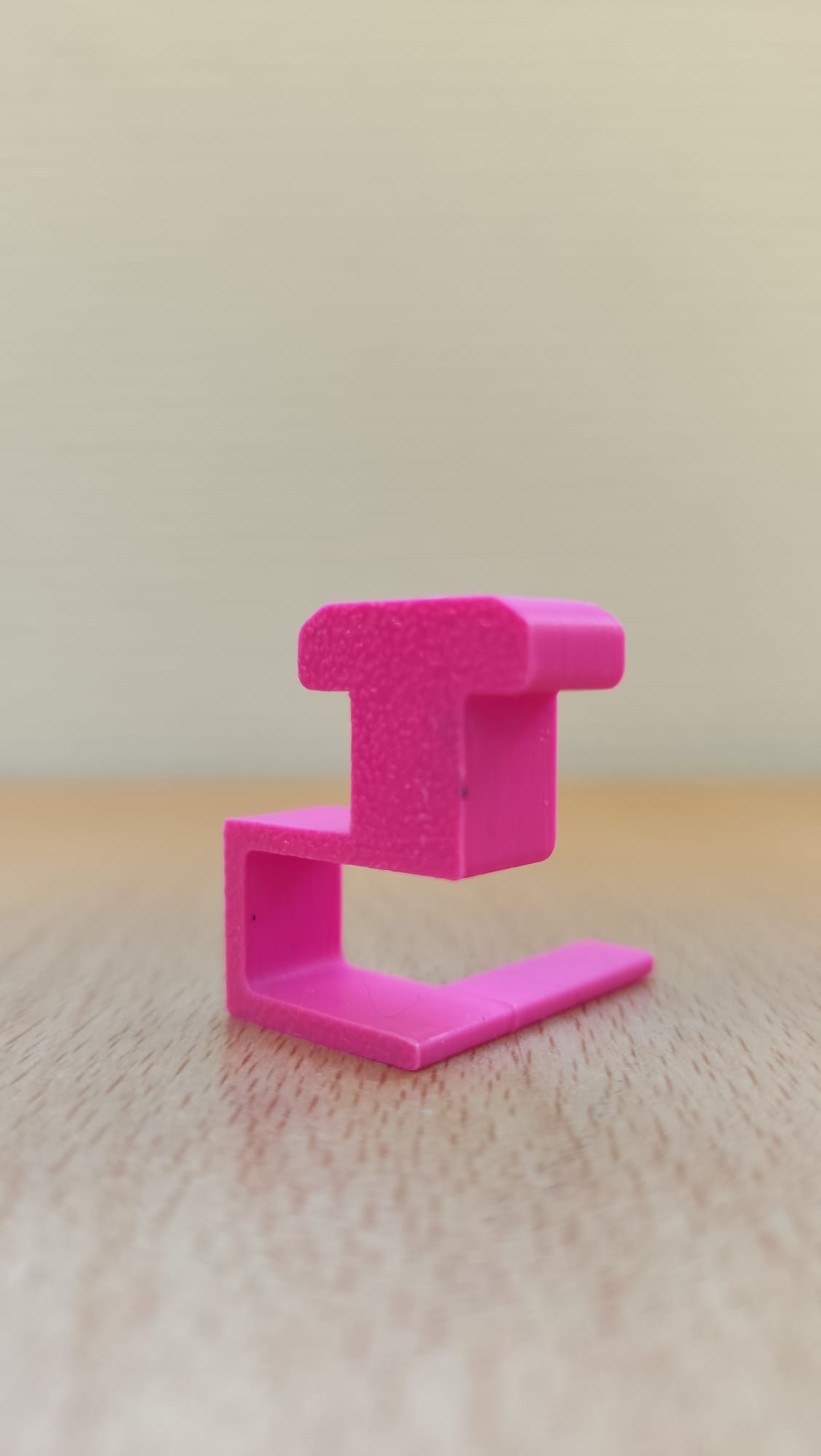
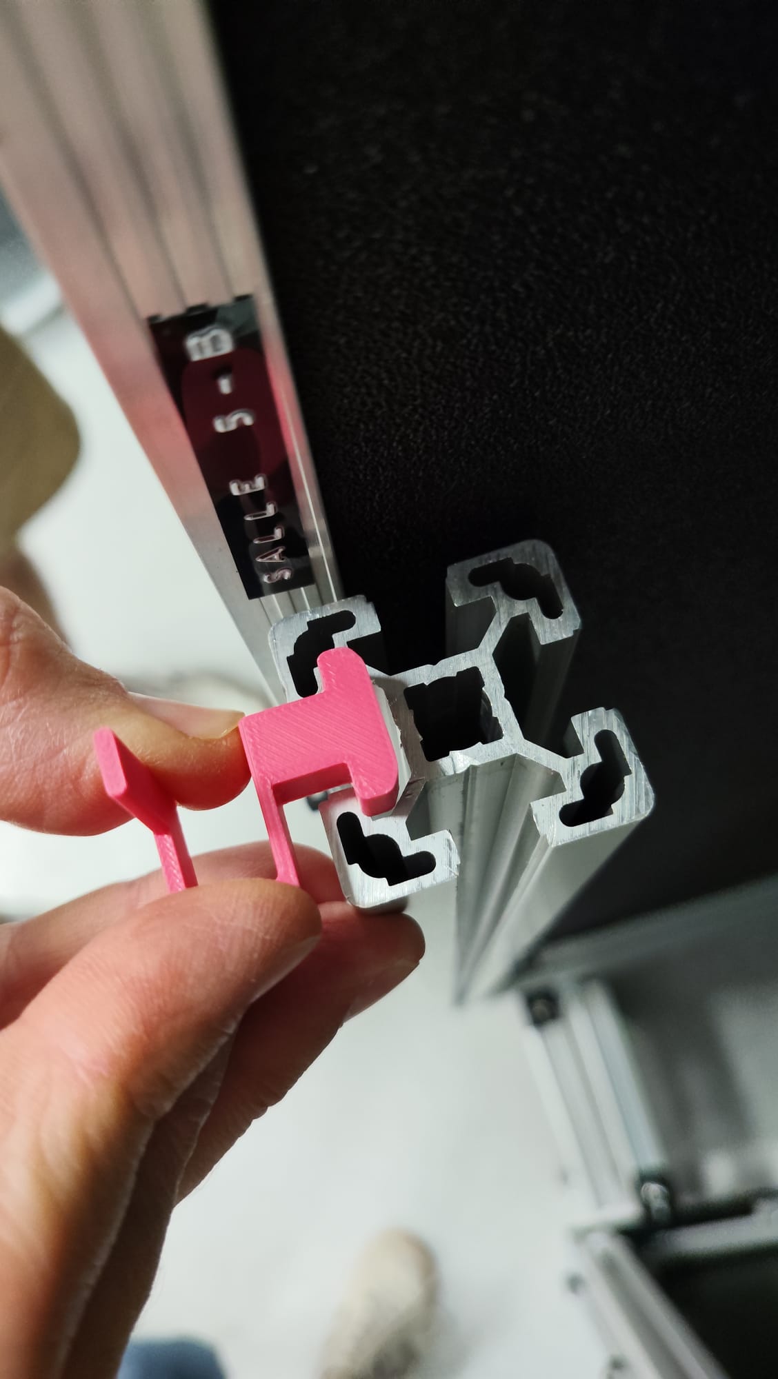
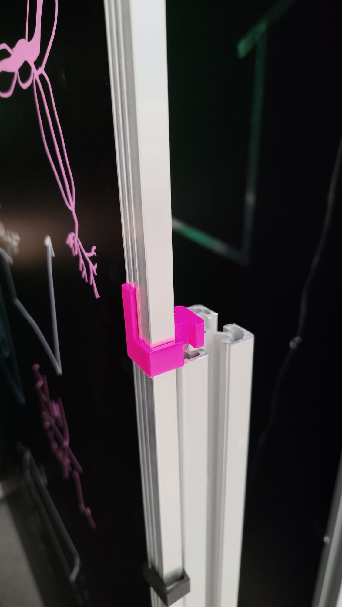 Link to the file : blocco pannelli prova 1.FCStd
2nd Prototype : Developed by reducing the upper interlocking part and extending the panel support base. Testing revealed an excessive reduction of the joint, preventing part insertion and panel adhesion.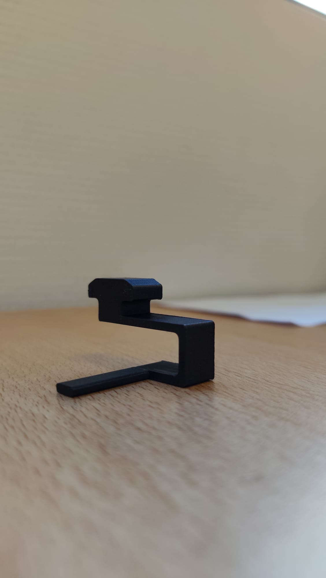
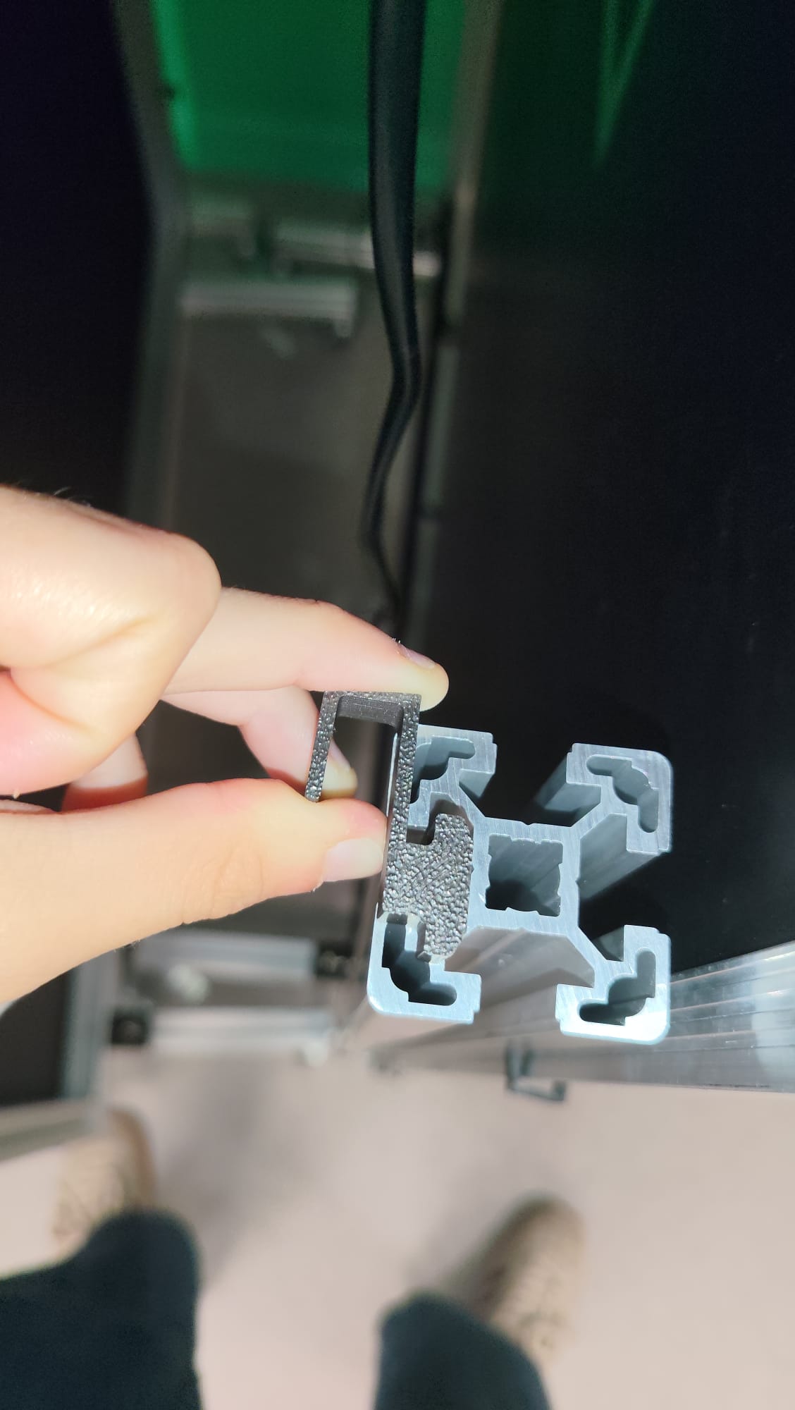
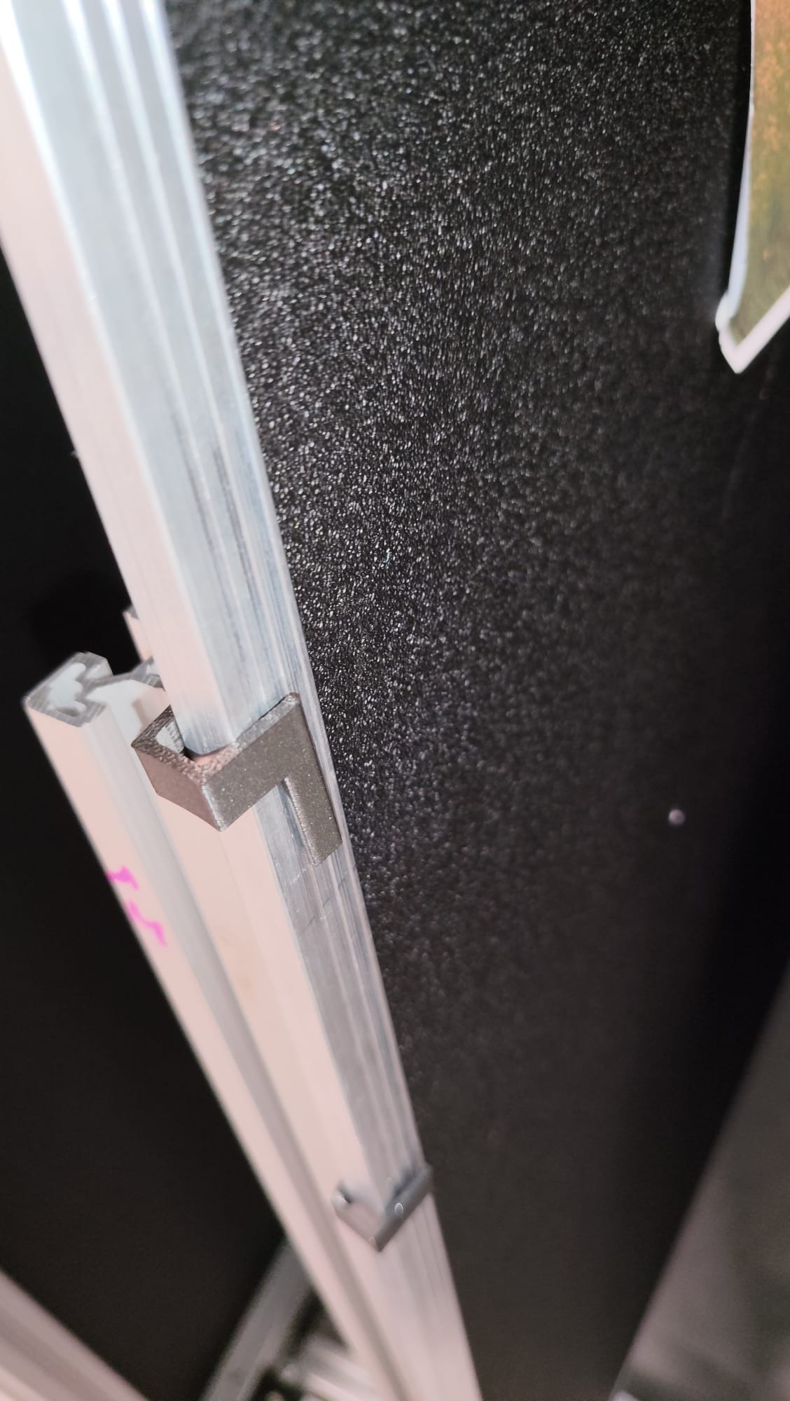
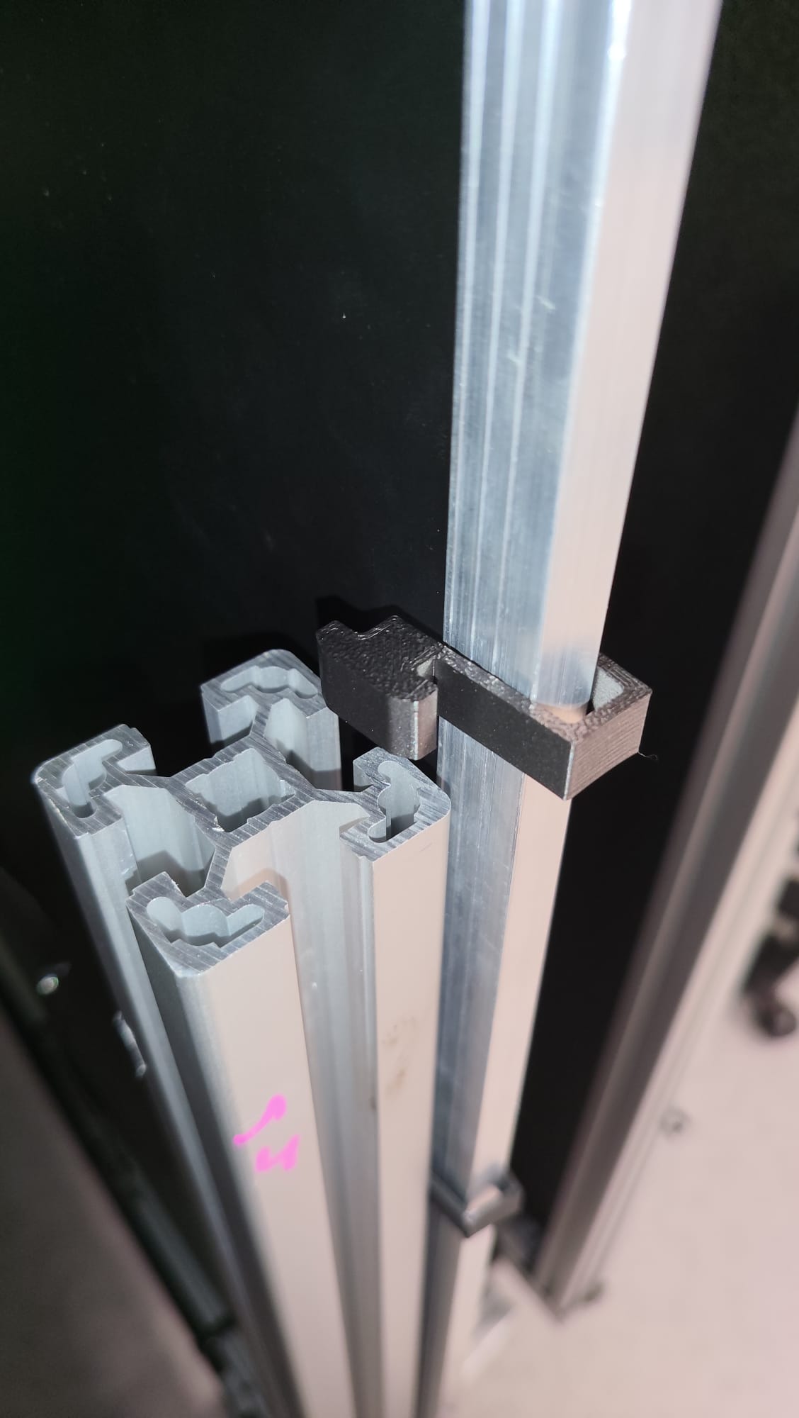 Link to the file : blocco pannelli prototipo 2.FCStd
3rd Prototype : Corrected in the upper section and modified by adding a lateral incline. The part adhered to the panel, but still presented insertion difficulties into the profile slot.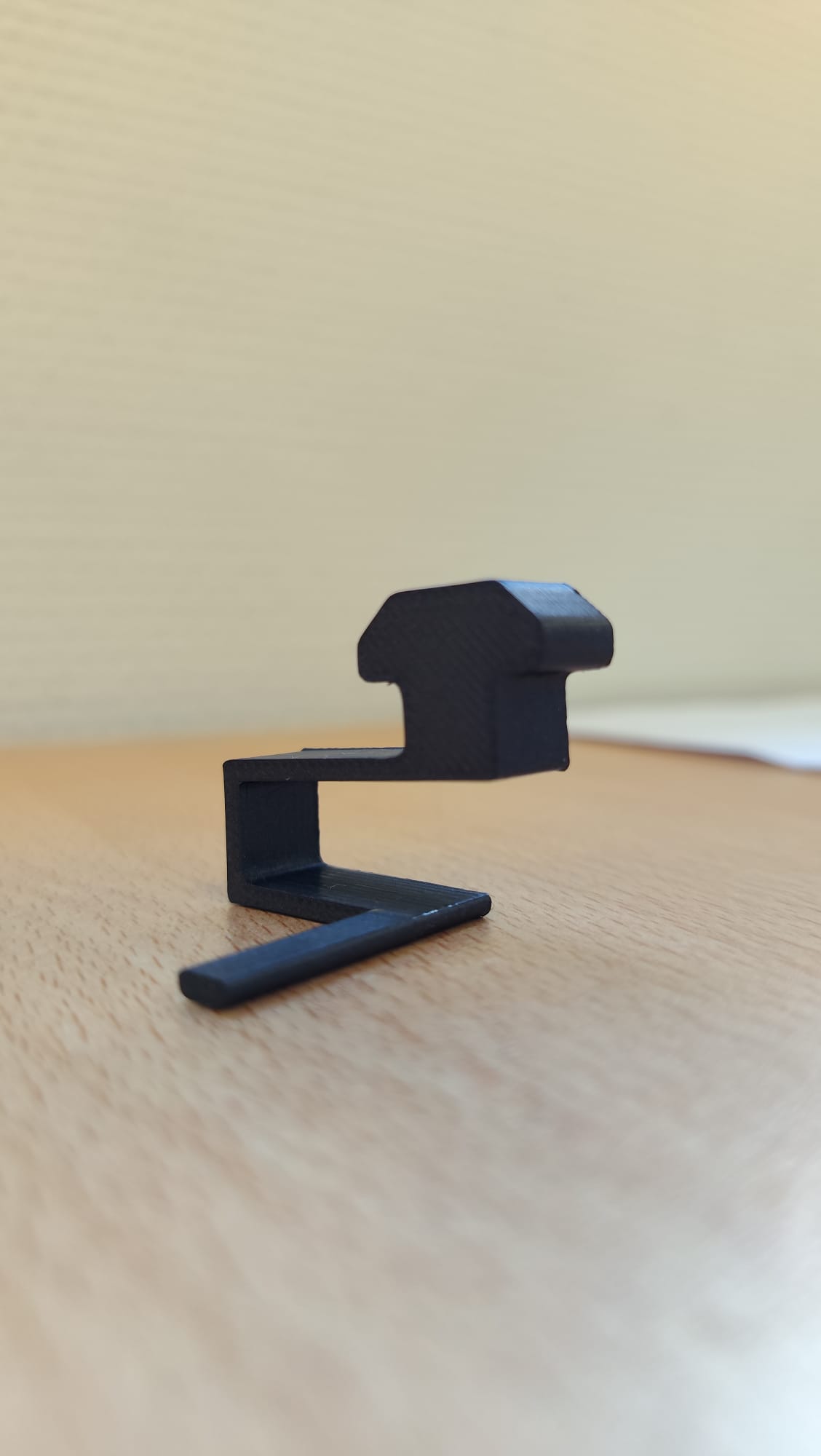
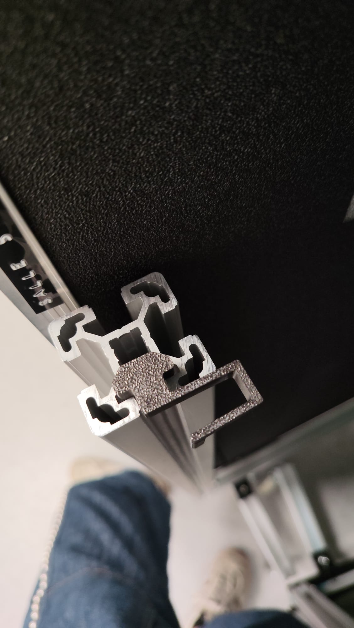
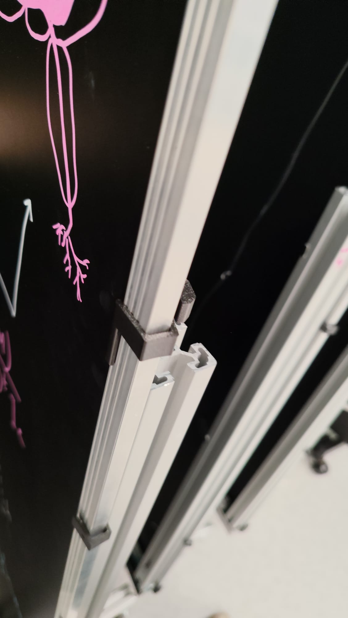
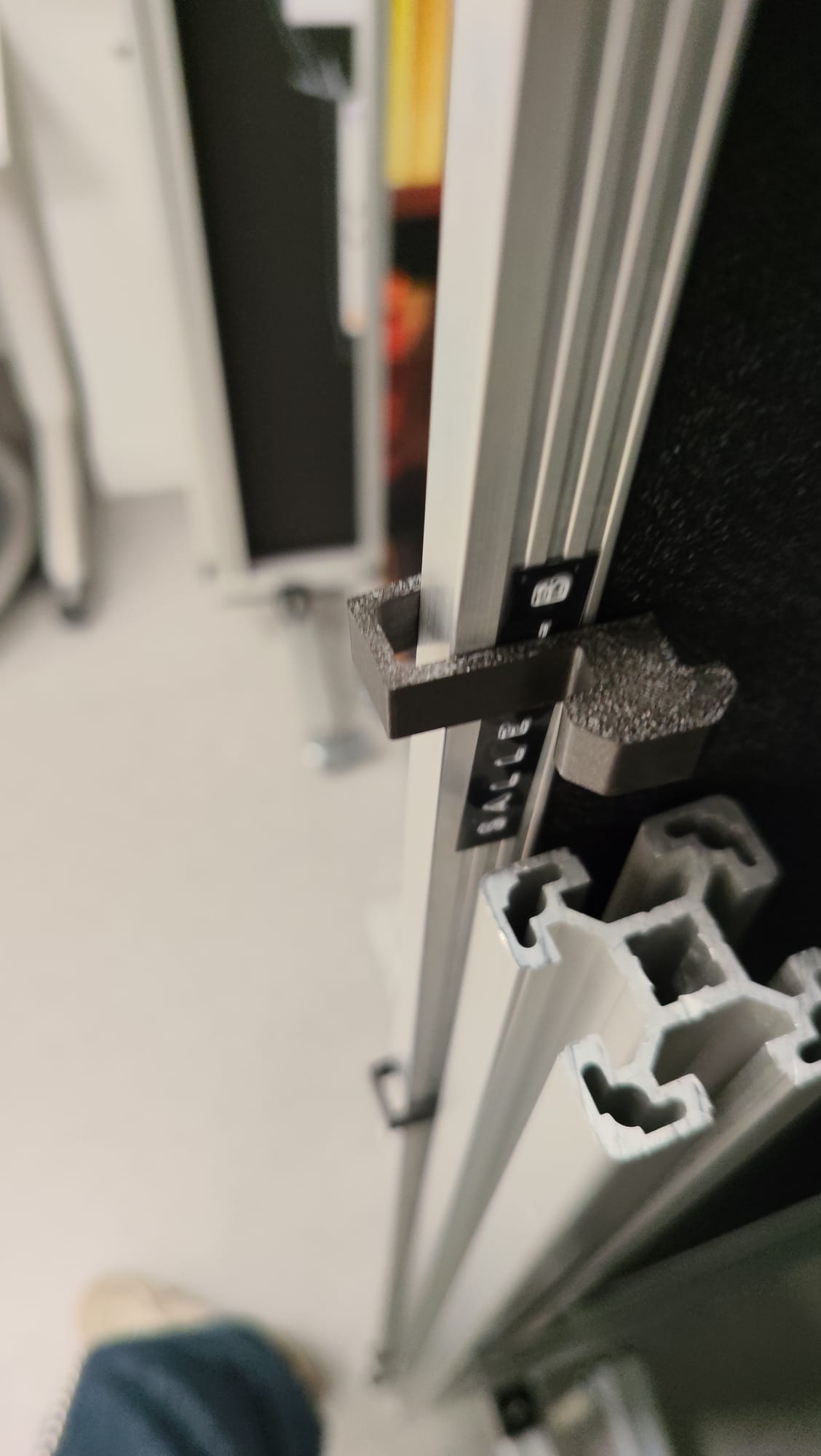 Link to the file : blocco pannelli prototipo 3.FCStd
4th Prototype : Refined the incline, ensuring proper insertion into the profile. Structural details were added, such as a rounded support surface on the panel side and a central ridge along the edges to increase the mechanical strength of the PLA. However, during removal from the profile, improper stress caused it to break.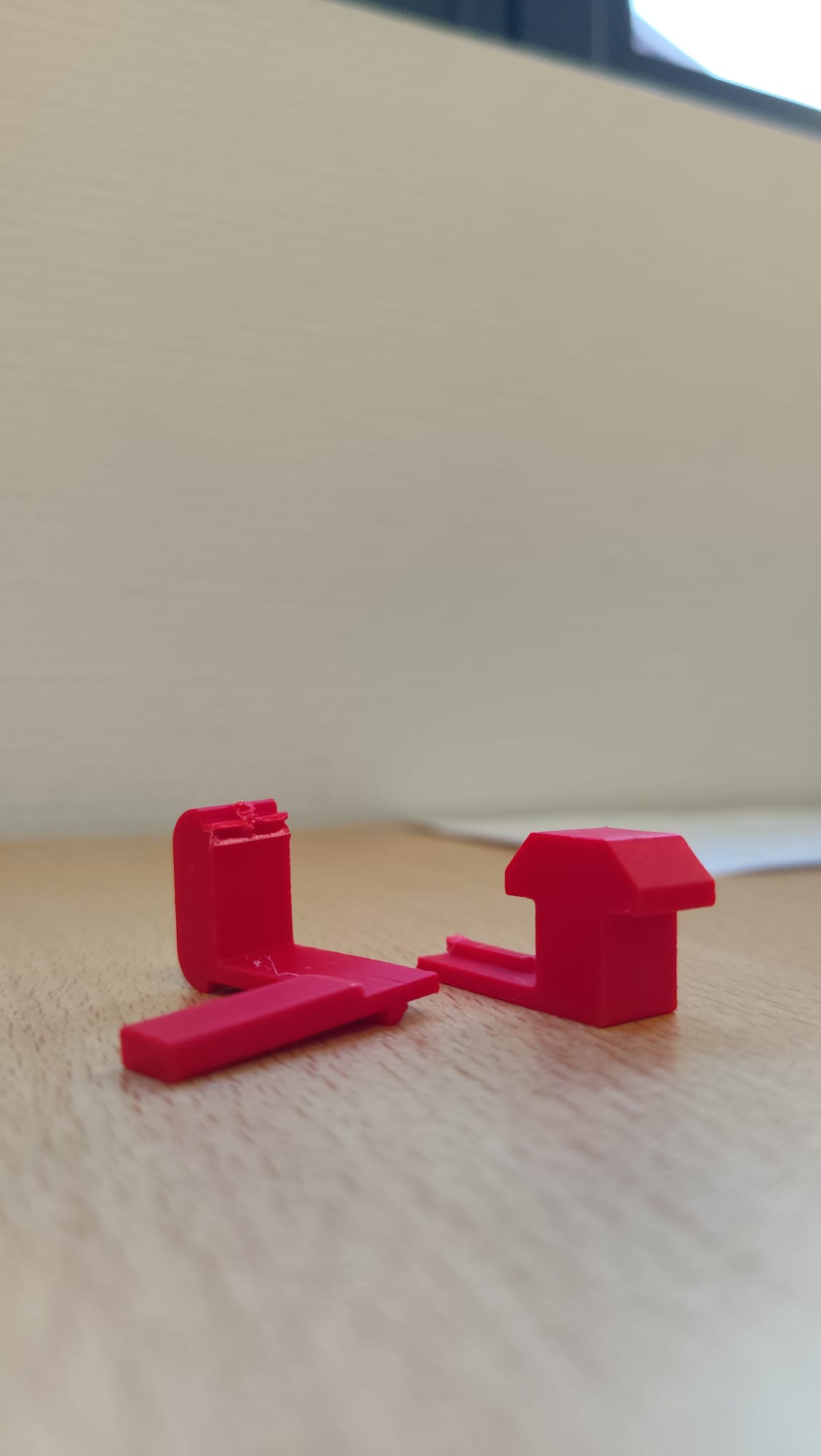
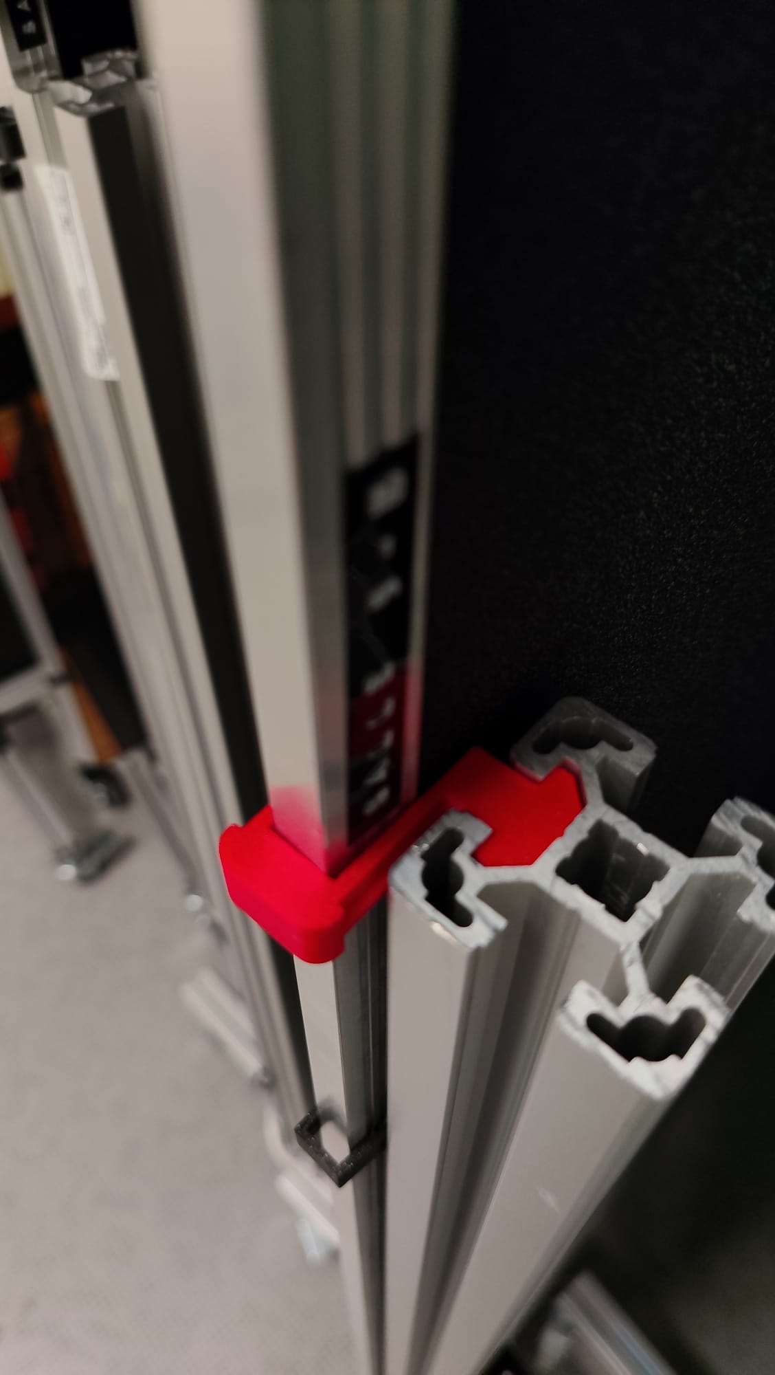
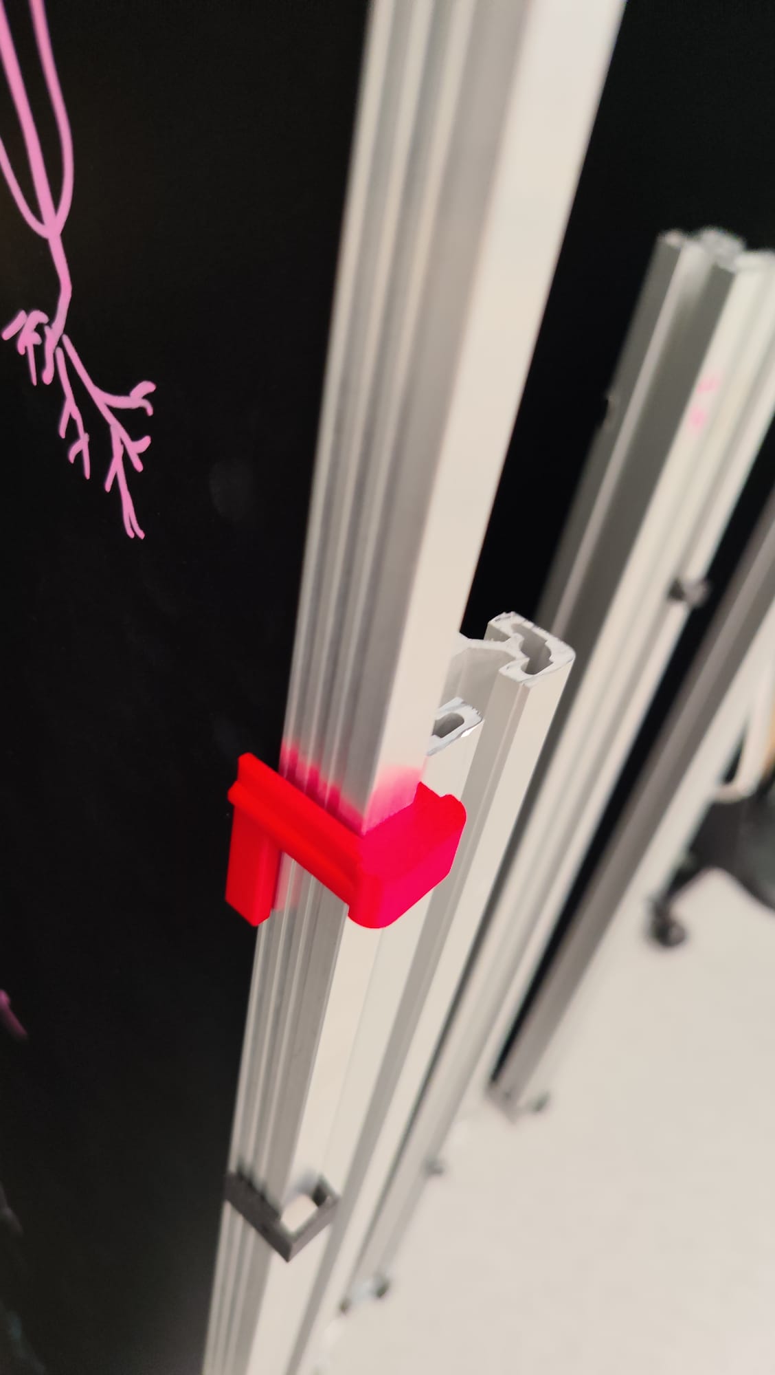 Link to the file : blocco pannelli prototipo 4.FCStd
5th Prototype (Final Version) : Applied the final dimensional corrections (a few millimeters removed from the side and added to the bottom), achieving the final, functional component.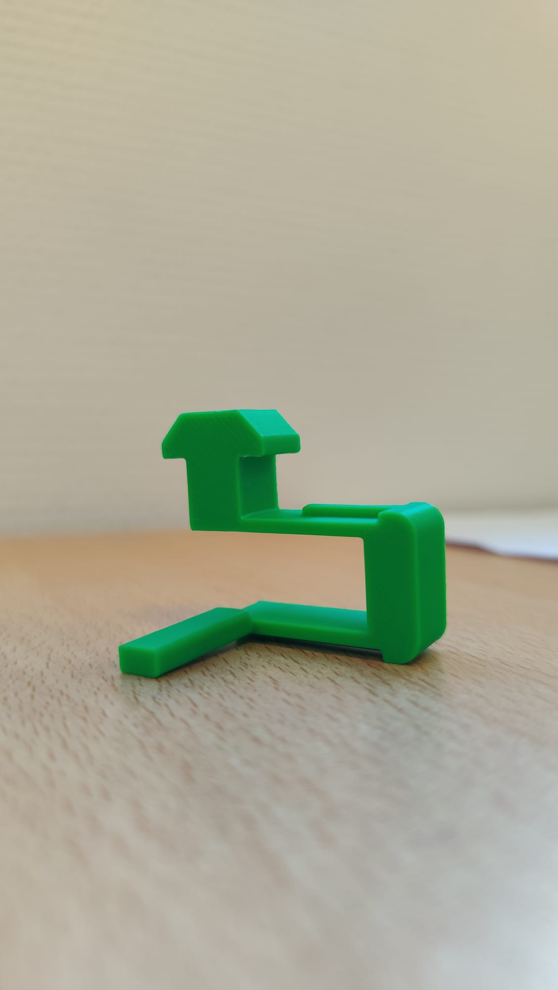
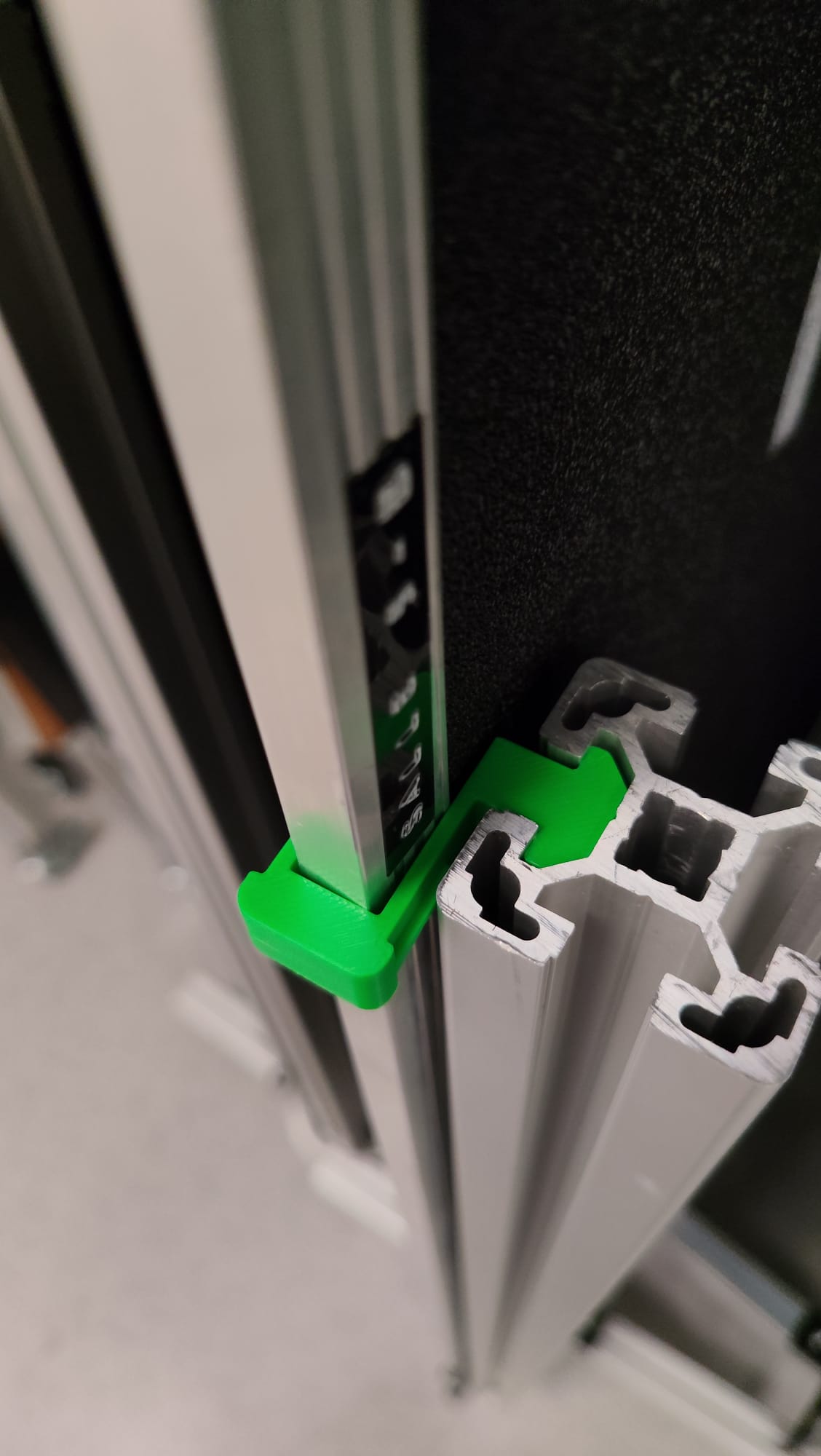
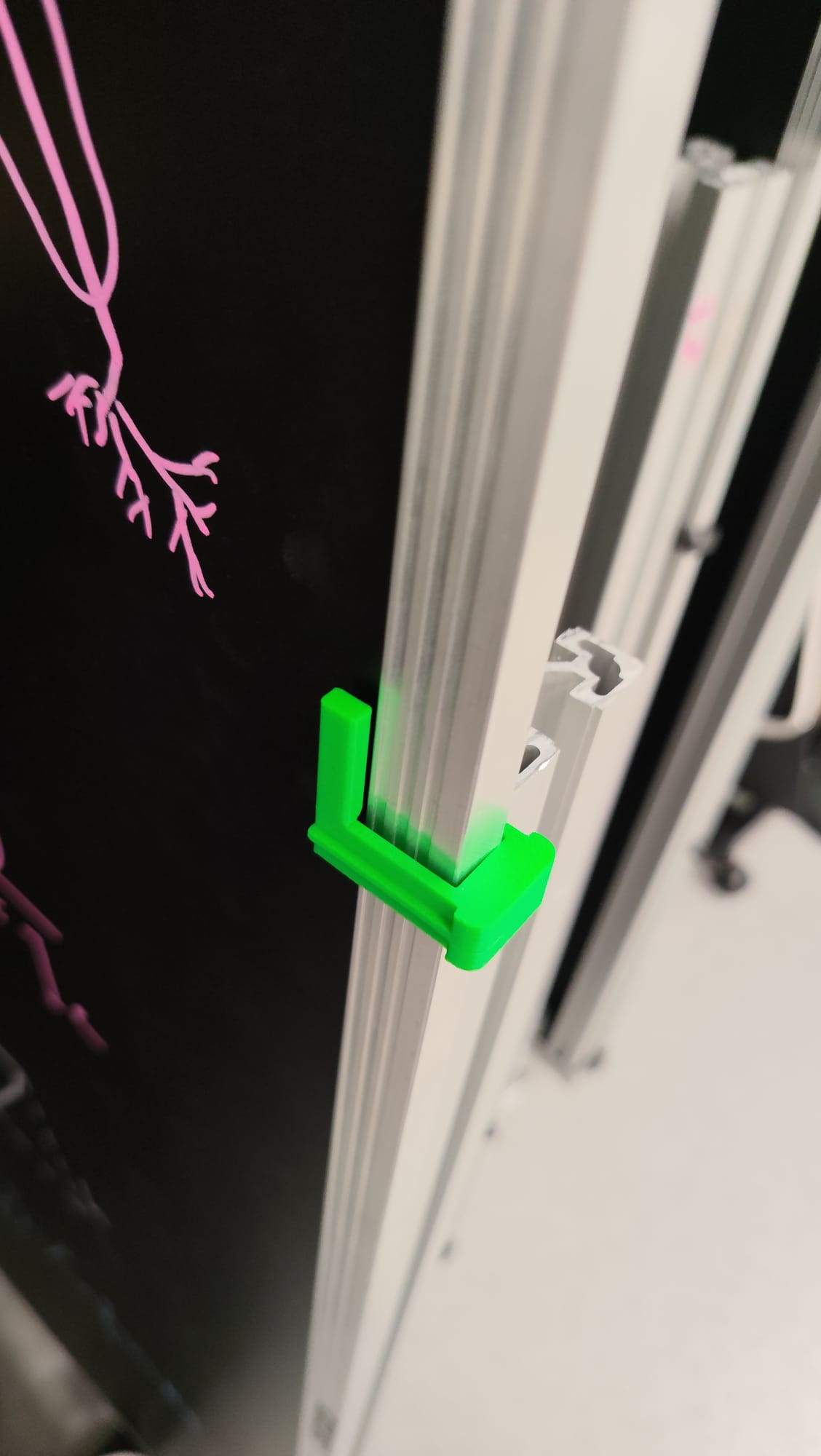 Link to the file : blocco pannelli prototipo 5.FCStd
4. CONCLUSION AND KEY LEARNINGS
The development of the component highlighted the effectiveness of the rapid prototyping process. The core of the activity lay in the systematic analysis of the critical issues identified in each prototype, which provided the necessary insights to correct errors and drive improvements in subsequent iterations, ultimately leading to the final result.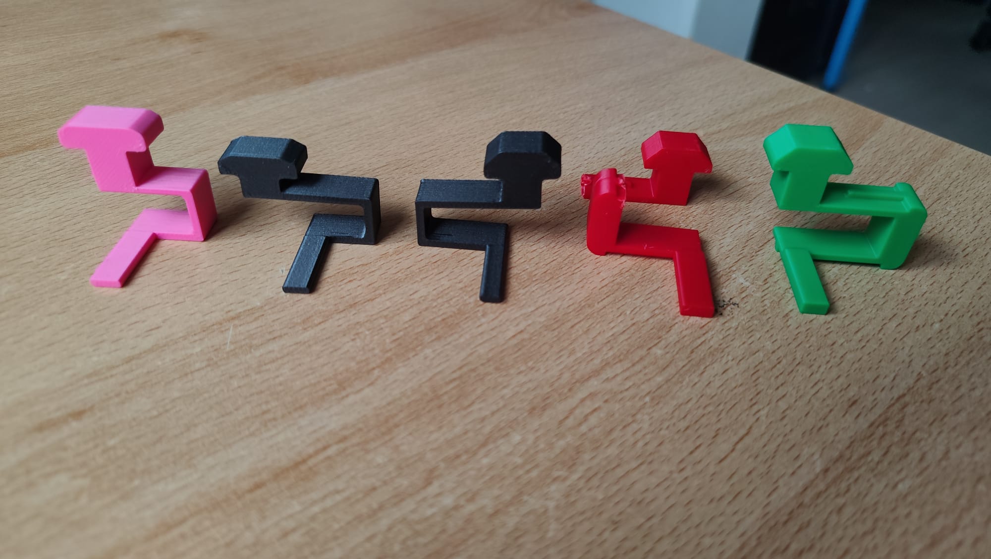
COMPONENTS FOR THE "ROCK CLIMBING ROBOTS" PROJECT
I designed the parts for the 'Rock Climbing Robots' projec.
PERFORATED PANEL
Panel size: 900x1400mm (usable hole grid area 800x1400mm).
Holes: ⌀3.4mm, with 15mm spacing.
There are 4968 holes in total (54x92)
On the sides, it has 6 holes on one side and 5 on the other because the first 4 holes (starting from the top) are for securing the panel to the frame using screws
While the 2 holes on the right and the 1 hole on the left are for securing the panel and frame together to the panel clamping using screws.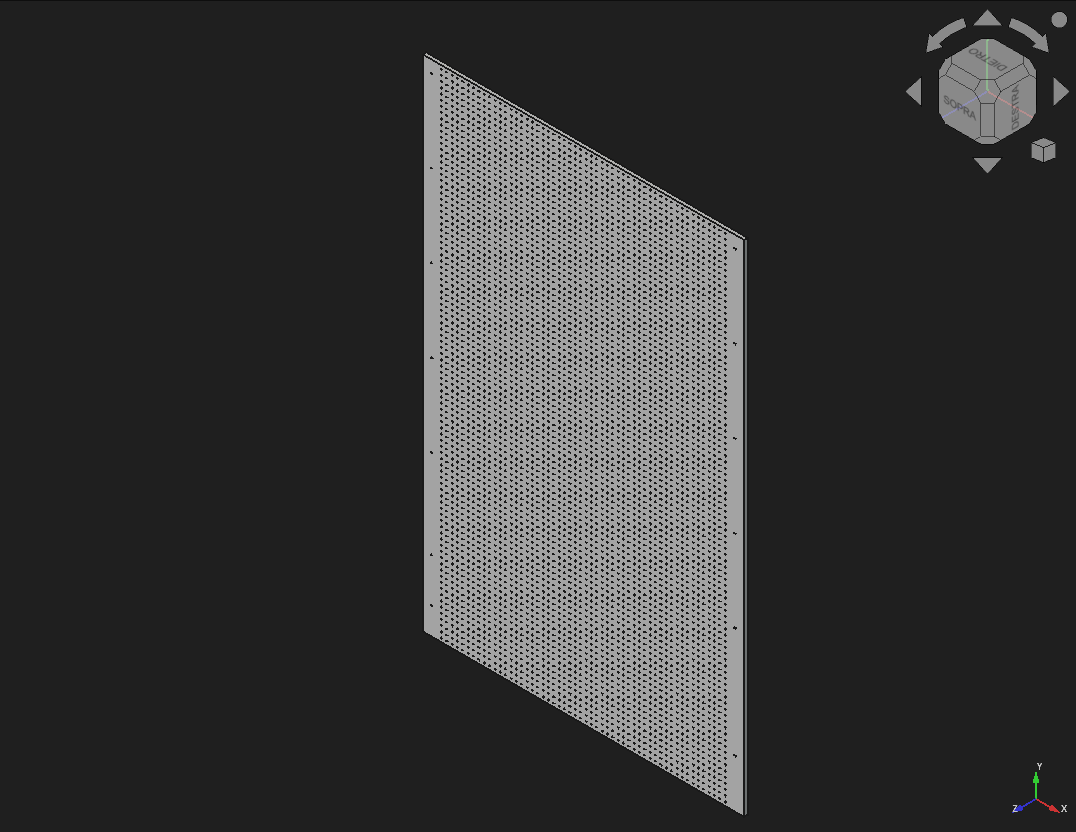
Link to FREECAD file : Perforated_panel.freecad.FCStd
Link to SVG file : SVG_Perforated_panel.svg
PANEL FRAME
Frame size: 900x1645mm.
Holes: ⌀4mm
Like the panel, the frame also has the 6 and 5 holes on the sides to join them together with screws.
At the top center, the frame features an extending rod measuring 200x45x45mm.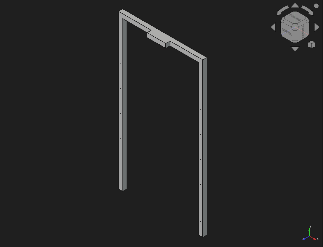
Link to FREECAD file : panel_frame.freecad.FCStd
PERFORATED BASE
Base size: 1100X500mm
Hole: ⌀4mm
On the base, there are 18 holes (9 on the right and 9 on the left).
These holes are used to secure the base to the panel clamping using screws.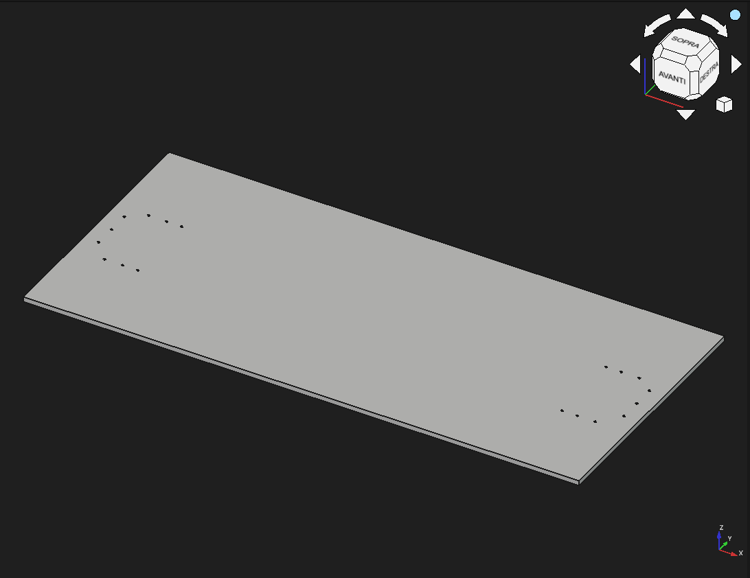
Link to FREECAD file : Perforated_base.freecad.FCStd
Link to SVG file : SVG_Perforated_base.svg
PANEL CLAMPING
For the panel clamping I had to design two prototypes before arriving at the final piece.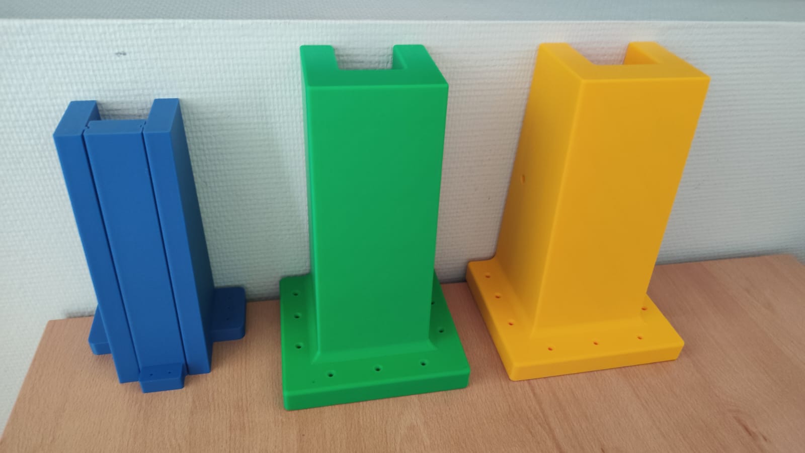
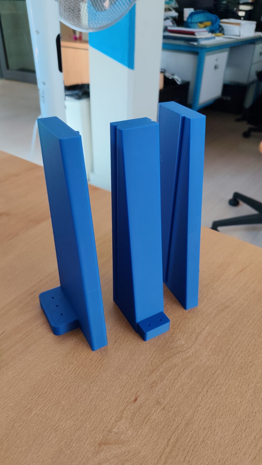
1st Prototype: The first prototype is very different from the others because it is divided into 3 pieces, as it was too large to fit in the 3D printer; therefore, the only solution was to make multiple parts to join together (the part in the photo is printed to scale with reduced dimensions).
The biggest problem was that having multiple parts joined together significantly decreased the part's strength. Additionally the base containing the holes for the screws to attach the clamping to the base was not a single piece like in after parts but separate and smaller sections which also reduced the overall strength.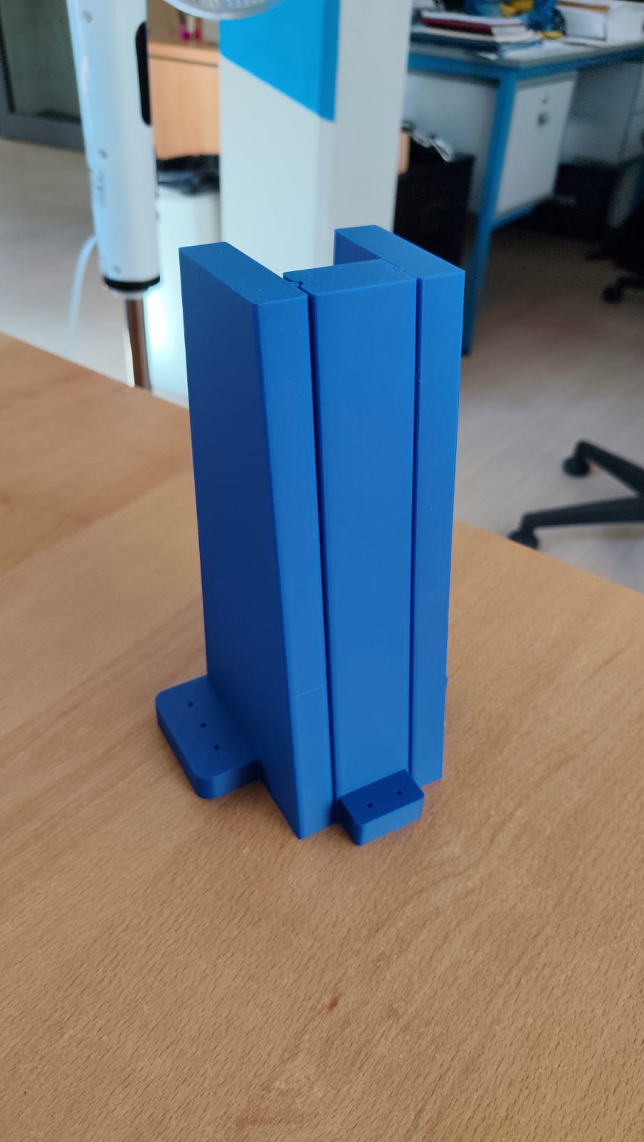
2nd Prototype: Before designing the second prototype, I performed structural calculations regarding the weight and forces that the two clampings would have to withstand.
To avoid dividing the clamping into three parts, I reduced the height from 300 to 250mm.
To increase strength, I joined the bottom section where the screw holes are located.
Another modification I made to increase strength was filleting all sides of the clamping.
The problem with this prototype was that the holes were too tight, so the screws did not fit properly into the clamping.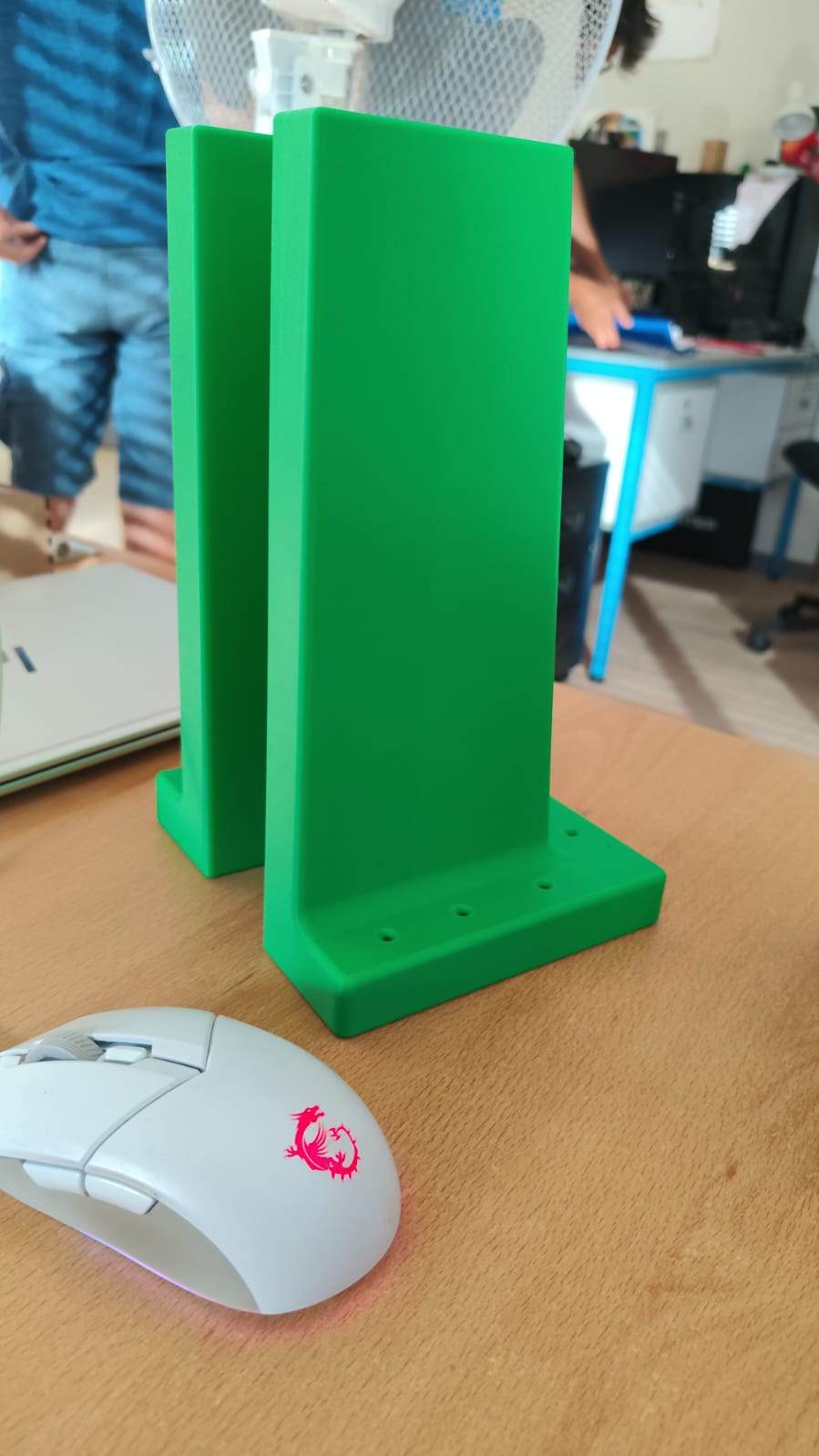
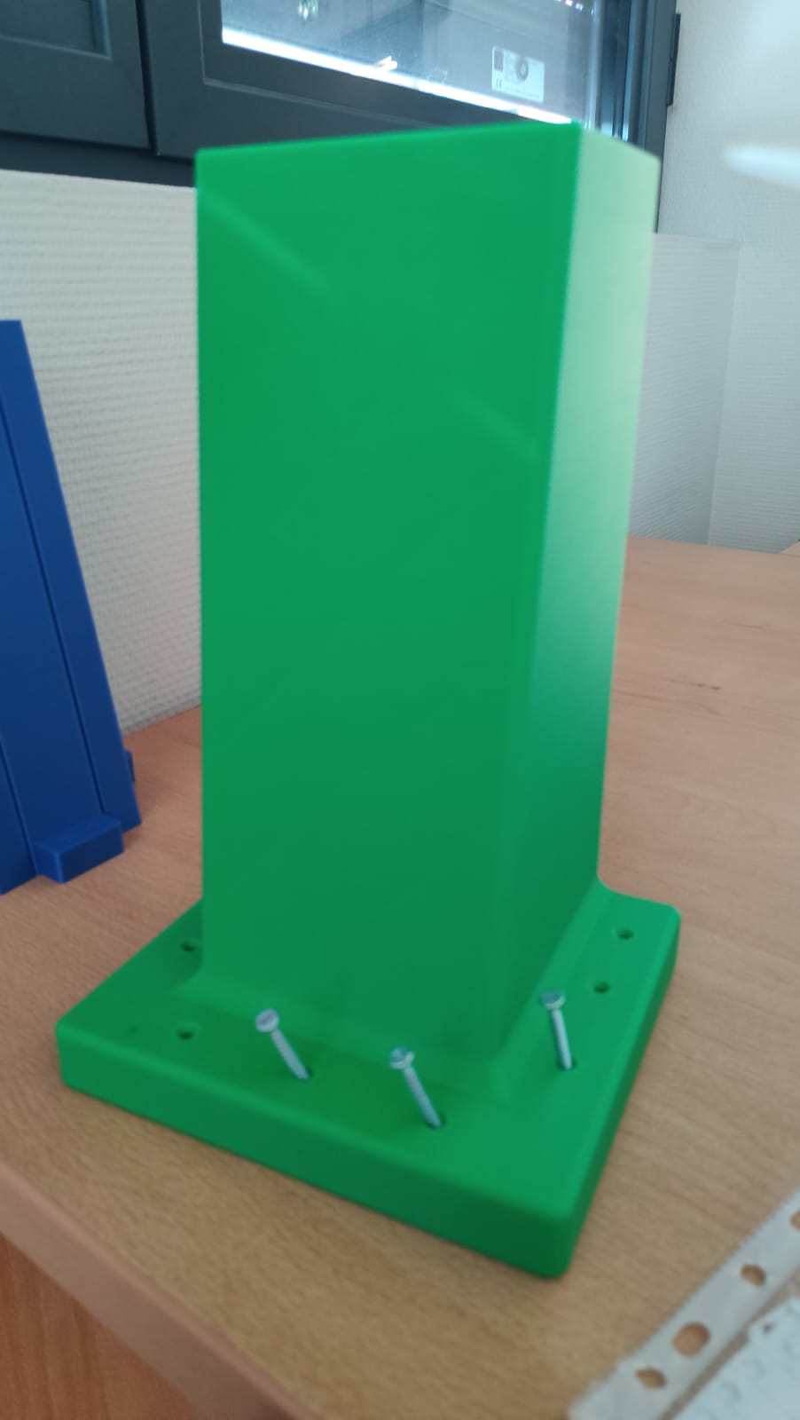
Final Piece: In the final piece, I increased the diameter of the holes and added side holes to lock the panel and frame together (2 on one side and 1 on the other).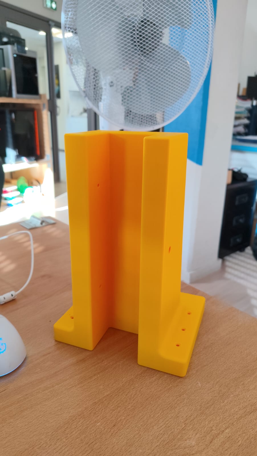
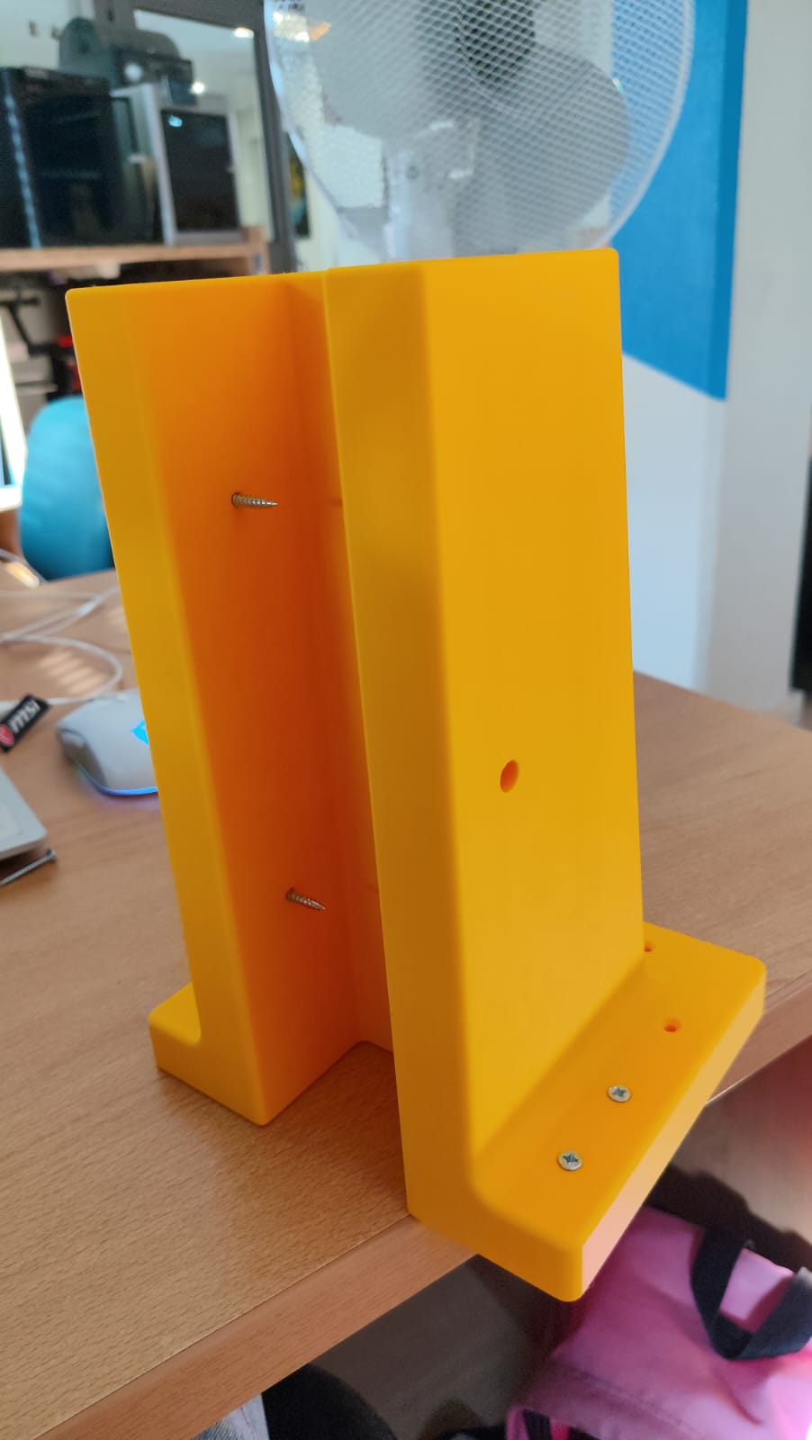
Link to FREECAD file : panel_clamping.freecad.FCStd
Link to GCODE file : panel_clamping.gcode.3mf
LASER CUT BOX
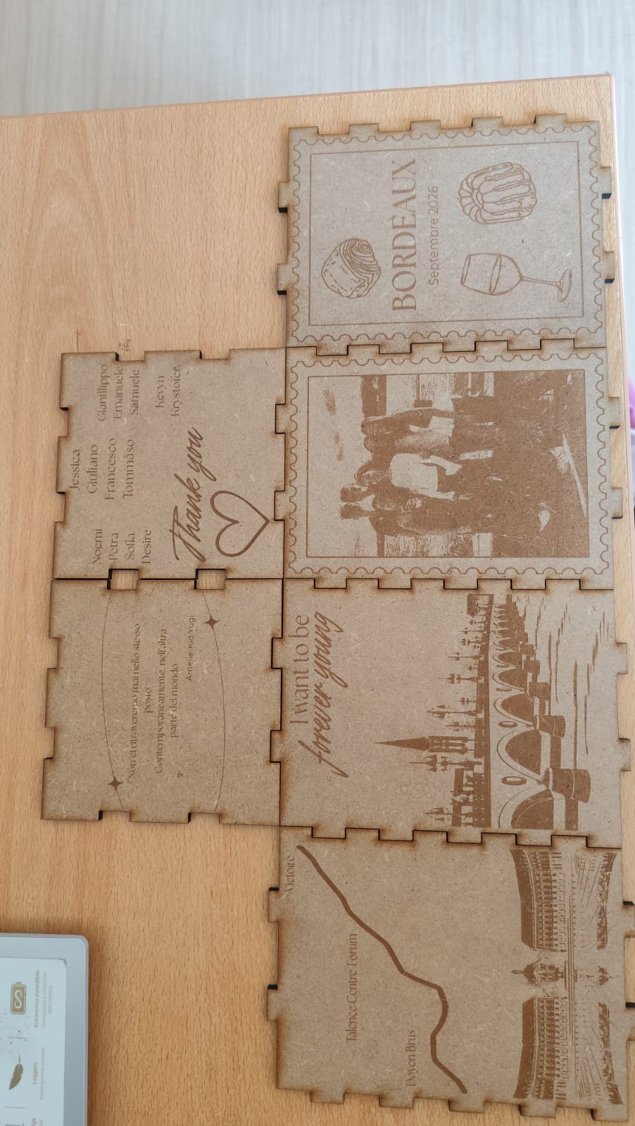
Link to SVG file : SVG_bordeaux2026_new.svg
Link to SVG file : SVG_bordeaux2026_soptra.sotto.svg