Cyprien Lopez
- Contenu
- Cyprien Lopez
- Informations sur les cartes électroniques
- Informations about electronic cards
Research on interior/exterior conditions of the hive
https://www.snapiculture.com/wp-content/uploads/2021/10/BeeHave_Etat_de_lart.pdf
Open source similar projects already existing
Connected Hive Monitoring an open source Hakster.io's project from FireCrackers
https://www.hackster.io/firecrackers/connected-hive-monitoring-9c3ee8#story
Made by a group of students from 2nd year at Polytech Sorbonne and Plaisir Village Animation association.
In response at Colony Collapsse Disorder issues.
Their solution was to create beehive monitoring. They added sensors for : weight, temperature, humidity and luminosity. Communicate with LoraWan, TTN and Beep.
Electronic card
Power module :
- 3.7V, 1050maH battery, solar pannel, LiPo Rider Pro.
- 3.3V voltage regulators x2 -> power system and show battery percentage
-> shutdown sensors to reduce electric consumption
Sensors :
- luminosity : voltage/current sensor INA219 with solar panel
- temp and humidity in and out : DHT22
- temp in: 2 or 3 temp probes DS18B20
- weight sensor : load cell and an amplifier HX711
System:
- LoRa-E5 module
- Nano 33 BLE Sense
Others interresting things from similar projects
https://www.hackster.io/bumblebeez/connected-hive-9ff416
- TPL5110 : low energy consumption module, shut down componants and wake them up only when needed working with a timer
- usually use TTN LORA
https://www.hackster.io/bee-efficient/connected-bee-hive-project-remote-hive-monitoring-e7cd34
Interesting news about frequency analysis of the colony. Focus on low freq 98-583 Hz with 10 steps of 48 Hz :
- 350 Hz -> quacking = multiple queens are present and would fight to become the queen of the colony
- 450 Hz -> High spectral density that can indicate tooting which happens when a bee signals that she is the future queen to be born (allowing other potential queens not to be released by workers).
- 510 Hz -> can indicate that the colony is in bad health.
https://pmc.ncbi.nlm.nih.gov/articles/PMC7711573/
- 5k Hz (with 15-16k Hz harmonics) can mean guard bees are against an hornet attack
Maladies
| Maladies | Conséquences | Détection | Sources |
| acarapidose | s'installe dans la tréchée des abeilles, s'y reproduit et pond -> fatigue l'abeille et l'empèche de voler -> grouillement et sautillement devant l'entrée du ruchier (printemps surtout), 15j pour avoir une nouvelle génération de larve | L’acarapisose ne peut être détectées en laboratoire qu’en utilisant un microscope ou par une méthode immuno-enzymatique (ELISA). Il n’y a aucune méthode fiable pour la détection des infections primaire | - https://www.blv.admin.ch/blv/fr/home/tiere/tierseuchen/uebersicht-seuchen/alle-tierseuchen/tracheenmilben-krankheit--acarapis-woodi-.html#158_1456315641844__content_blv_fr_home_tiere_tierseuchen_uebersicht-seuchen_alle-tierseuchen_tracheenmilben-krankheit--acarapis-woodi-_jcr_content_par_tabs - https://www.woah.org/fileadmin/Home/fr/Health_standards/tahm/3.02.01_Acarapisose_2008.pdf |
| nosemose | parasite qui attaque les cellules intestinales des abeilles et dérègle leur digestion ainsi que leur système immunitaire, Abeilles faibles et désorientées devant la ruche, traces de Diarrhées dans et autour de la ruche | clinique ou en labo | - https://www.naturapi.com/naturapicafe/sante-de-la-ruche-tout-savoir-sur-la-nosemose/ - https://gds19.org/Docs/PDF/UP/2015/UP-01-10-15.pdf |
Sensors
Humidity
here are few research on the most used humidity sensors.
| Sensor | Type | Humidity Range (%) | Humidity Accuracy (%) | Temperature Range (°C) | Temperature Accuracy (°C) | Power Supply (V) | Interface | Power Consumption | Waterproof | Price (€) classique / waterproof | Notes |
| SHT20 | Humidity + Temperature | 0-100 | ±3 | -40 to +125 | ±0.3 | 2.1-3.6 | I2C | Moderate | Yes | 5 - 25 | Good for harsh environments, moderate precision, affordable. |
| SHT31-DIS-P | Humidity + Temperature | 0-100 | ±2 | -40 to +125 | ±0.3 | 2.4-5.5 | I2C | Low (<1 mA) | Yes | 5 - ? | High precision, robust, suitable for demanding applications. |
| AM2315 | Humidity + Temperature | 0-100 | ±2 | -40 to +80 | ±0.3 | 3.3-5.5 | I2C | Moderate | Yes | Durable, ideal for outdoor or high-humidity conditions. | |
| HDC1080 | Humidity + Temperature | 0-100 | ±2 | -40 to +85 | ±0.2 | 2.7-5.5 | I2C | Ultra-low (<1 µA in sleep mode) | Optional | 15-25 | Low-power, compact, great for battery-powered systems. |
| DHT22 (AM2302) | Humidity + Temperature | 0-100 | ±2 | -40 to +80 | ±0.5 | 3.3-6 | Digital | Low (~2.5 mA during measurement) | Optional | 8 | Affordable, but less robust in extreme environments compared to others. |
| DHT11 | Humidity + Temperature | 20-90 | ±5 | 0 to +50 | ±2 | 3.3-5.5 | Digital | Very low (~2 mA) | No | 5 | Very low cost, limited accuracy, best for basic applications. |
| DS18B20 | Temperature only | - | - | -55 to +125 | ±0.5 | 3-5 | 1-Wire | Low (~1 mA active, ~0.75 mA idle) | Yes | 5 - 9 | Fully waterproof, ideal for temperature monitoring in wet or confined spaces. |
| BME280 | Humidity + Temp + Pressure | 0-100 | ±3 | -40 to +85 | ±0.5 | 1.8-3.6 | I2C/SPI | 0.1 μA (idle), 1.8 μA (active), 3,6 μA (active with pressure) | No | 4 | Multifunctional sensor, measures pressure as well, suitable for compact projects. |
| BME680 | Humidity, temperature, pressure, gaz | 0-100% | ±3 % r.H | -40 à +85 °C | ±0,5 °C à 25 °C | 1,71 V à 3,6 V | I2C, SPI | 0.15 µA (idle) 2.1 µA (active), 3.15 (active with pressure too) | No | 7 | overkill, peu de consommation |
Comparative table
here are few research on the most used humidity sensors.
| Sensor | Type | Humidity Range (%) | Humidity Accuracy (%) | Temperature Range (°C) | Temperature Accuracy (°C) | Power Supply (V) | Interface | Power Consumption | Waterproof | Price (€) classique / waterproof | Notes |
| SHT20 | Humidity + Temperature | 0-100 | ±3 | -40 to +125 | ±0.3 | 2.1-3.6 | I2C | Moderate | Yes | 5 - 25 | Good for harsh environments, moderate precision, affordable. |
| DHT22 (AM2302) | Humidity + Temperature | 0-100 | ±2 | -40 to +80 | ±0.5 | 3.3-6 | Digital | Low (~2.5 mA during measurement) | Optional | 8 | Affordable, but less robust in extreme environments compared to others. |
| DS18B20 | Temperature only | - | - | -55 to +125 | ±0.5 | 3-5 | 1-Wire | Low (~1 mA active, ~0.75 mA idle) | Yes | 5 - 9 | Fully waterproof, ideal for temperature monitoring in wet or confined spaces. |
| BME280 | Humidity + Temp + Pressure | 0-100 | ±3 | -40 to +85 | ±0.5 | 1.8-3.6 | I2C/SPI | 0.1 μA (idle), 1.8 μA (active), 3,6 μA (active with pressure) | No | 4 | Multifunctional sensor, measures pressure as well, suitable for compact projects. |
| BME680 | Humidity, temperature, pressure, gaz | 0-100% | ±3 % r.H | -40 à +85 °C | ±0,5 °C à 25 °C | 1,71 V à 3,6 V | I2C, SPI | 0.15 µA (idle) 2.1 µA (active), 3.15 (active with pressure too) | No | 7 | overkill, peu de consommation |
Communication
What's used in Mellia
Node-red est un outil de développement basé sur les flux. Il sert ici à récupérer les données en provenance du broker MQTT fournit par TTN et à les enregistrer dans une base de donnée influxDB. Les ressources pour le déployer se situe dans le répertoir software.
Pour se connecter au broker on commence par ajouter le module MQTT à l'interface node red en suivant ce tutoriel : https://www.thethingsnetwork.org/forum/t/mqtt-in-node-red-howto/39909
NB : nous utilisons Orange plutôt que TTN pour recevoir les données LoRa mais le principe est le même
OpenHive Scale card
add here sch of the card
Here is the schematic of the electronic card of the open hive scale. We want to "add" it on our own system a connected hive, Plan Bee, instead of the initial strain gauge Mellia was using. Then I started to work on this file, first i divided the sheet in few groups based on what they do in our system.
1.8 V to 3.6 V power supply
–40 °C to 105 °C temperature range
Shutdown mode: 31 nA (VDD = 3 V)
Standby ( RTC) mode:360 nA (VDD = 3 V)
Stop2 (+ RTC) mode: 1.07 µA (VDD = 3 V)
Active-mode MCU: < 72 µA/MHz (CoreMark®)
Active-mode RX: 4.82 mA
Active-mode TX: 15 mA at 10 dBm and 87 mA at 20 dBm (LoRa® 125 kHz
Plan Bee elec card
Now that we studied both cards from Mellia and open hive scale, we are going to do our own card which is basically a fusion of the other two with our upgrades (at least we hope). Here bellow is a list of the componants we kept and few usefull informations to do the schematic.
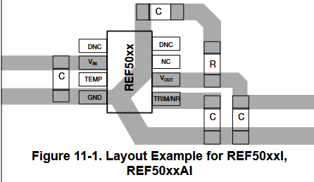
- REF5050AID : reference voltage
The REF5050AD previously used no longer appear on mouser, here an alternative version.
• Place the power-supply bypass capacitor as closely as possible to the supply and ground pins. The
recommended value of this bypass capacitor is from 1μF to 10μF. If necessary, additional decoupling
capacitance can be added to compensate for noisy or high-impedance power supplies.
• Place a 1μF noise filtering capacitor between the NR pin and ground.
• The output must be decoupled with a 1μF to 50μF capacitor. A resistor in series with the output capacitor is
optional. For better noise performance, the recommended ESR on the output capacitor is from 1Ω to 1.5Ω.
• A high-frequency, 1μF capacitor can be added in parallel between the output and ground to filter noise and
help with switching loads as data converters.
- ESP8266
| GPIO0 | GPIO2 | GPIO15 | CHIP_PD / Enable | |
| normal mode | 3.3V | 3.3V | GND | 3.3V |
| boot mode | GND | 3.3V | GND | 3.3V |
Upgrades ideas
The above version is what we did, but it's not designed to be the final version at this state it's only a prototype. So here you can see what we plained to do or even idea that we had and didn't had time to develop.
- Combine the two MCU
As none of us were really familiar with those MCU we choosed to keep both of them. By doing that we could keep a big part of the programation that we already had which represent a massive time saver. For exemple one works easilly with the wifi and the other with LORA so both are usefull and we didn't want to take to much time now to learn from 0 a MCU that can deal with both. But obviously it would be better if everything on the card work with only one MCU.
- add optical sensor rotary encoder
As we can see on the mainboard file (kicad schematic for the scale) this were already an idea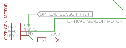
Informations sur les cartes électroniques
Comme expliqué précédemment, le projet PlanBee sera grandement inspiré de deux autres projets que sont Mellia et OpenHiveScale. Il est donc nécessaire de comprendre leur fonctionnement avant de s’attaquer à notre carte.
OpenHiveScale
Informations about electronic cards
As explained previously, the PlanBee project will be greatly inspired by two other projects: Mellia and OpenHiveScale. It is therefore necessary to understand how they work before tackling our card.
Why Mellia ?
Sensitive to the cause of bees and with a view to developing responsible digital technology, OpenStudio created the Mellia project with the aim of helping beekeepers. They propose to develop connected hives. The project is non-profit and there is no commercial model associated with it. They carried out their work in an open source, open hardware and open data manner. Their goal is to understand the needs of bees and protect them. Using big data and machine
learning analyses, they hope to develop a model capable of predicting risks in order to be able to react to them.
The Mellia Dadant 10 kit is a set of connected sensors making it possible to obtain essential information relating to the operation of a hive with the aim of monitoring the evolution of the colony while reducing the number of intrusive interventions and the movements of the beekeeper. This kit fits a Dadant 10 hive, the most used model currently
Electronic part
Once we studied the objectives of the project, and verified that it aligned with ours, we wereable to inform ourselves on how to achieve them. We therefore retrieved the electrical diagram, created with KiCad, from the Mellia github. All the components and their connections are detailed there, this allowed us, in a reverse engineering approach, to understand how the electronic card works.
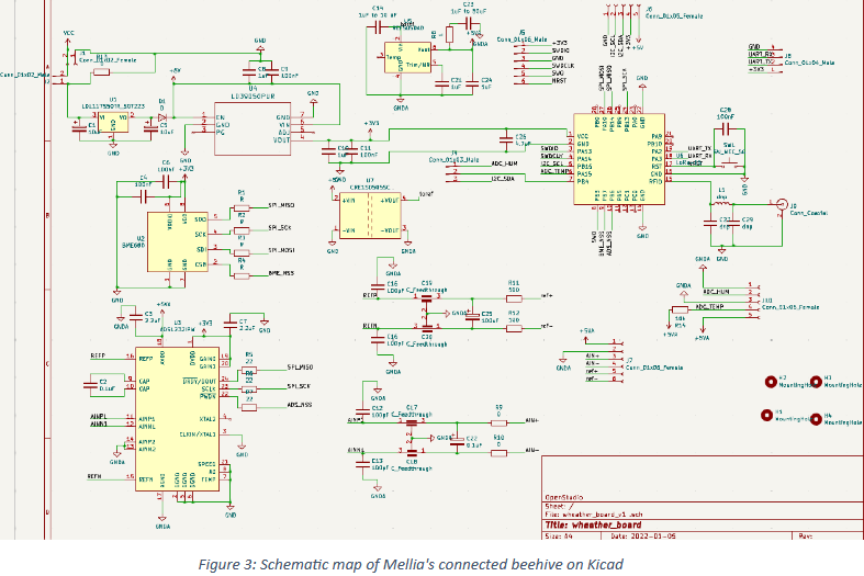
The circuit can be broken down into 4 main parts: the power supply, the microcontroller, the sensors, the data processing and transmission chain:
- Power Supply
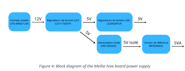
The system is powered by a UPS-4W6S/12V0 solar panel. The latter provides a voltage of 12V and also has an 18,000 mAh battery (which charges in 8 to 12 hours). This allows the system to remain sufficiently powered even outside of sunlight hours. However, not all components are powered by 12V and need different voltages. Voltage converters were therefore added.
The first need was a 5V output. It is possible to go from 12V to 5V using a linear regulator LD1117S50TR LDO (Low Dropout Regulator). Linear regulators use a transistor operating in linear mode to stabilize the voltage. Due to their simple design, they have the advantage of having low generation of electromagnetic noise. However, they are less energy efficient, the excess power being dissipated in the form of heat which causes losses. They are therefore only used for small voltage differences. We therefore go from 12V to 5V in this case.
For the same reasons, another linear regulator LDO LD39050PUR was chosen in order to convert the voltage from 5V to 3.3V
We now have all the voltages needed to power each component on the board. However, we must not forget that the main objective is to take precise measurements and it is therefore for this purpose that two other components have been added. When so many different components are connected on a power loop, there is a risk of high frequency disturbances and noise created by the power supply, the microcontroller or LoRa communication. To avoid this, an isolated DC-DC converter CRE1S0505SC was added. It receives 5V as input from voltage regulators and supplies 5V, isolated and insensitive to variations in the input, as output to the analog part of the circuit. This coupled with an analog ground plane, GNDA, separate from that of the rest of the card, reduces the risk of disturbances which would disturb the analog measurements.
In order to obtain good measurements, it is important to have a very precise power supply and motor. It is therefore with this in mind that once we have reduced the risk of disturbance, we will add a component which ensures that we have precisely the desired voltage. We achieve this thanks to the REF5050AID voltage reference which has very good accuracy (0.05%) and only slight drift due to temperature (3 ppm/°C).
- Sensors, microcontrollers, processing and transmission
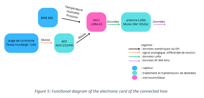
The main sensor is a BME 680, it gives us information on temperature, humidity, pressure, and VOCs (Volatile Organic Compound). This sensor is based on various technologies for each of these measurements. The temperature is obtained using a semiconductor thermistor. The measurement of relative humidity is based on the principle of the capacitive sensor measuring the absorption of water in a sensitive polymer. For pressure, it is thanks to a piezoresistive MEMS (Micro Electro Mechanical System) sensor which detects pressure variations by measuring the deformation of a membrane. Finally for gases these are VOCs which are detected by metal oxide (MOX) sensor by measuring the variation in resistance due to chemical interactions with the surrounding gases. It directly provides digital values ready to be sent to the microcontroller. A terminal block allows you to connect a Tedea Huntleigh 1242 strain gauge which is placed under the hive in order to know its mass variations. For a certain known measuring range, the load cell flexes slightly, thereby stretching or compressing wires mounted on the aluminum body. These movements cause a proportional variation in their electrical resistance. By using a Wheatstone bridge arrangement, a low voltage differential is obtained as an output signal.
To ensure high precision measurement, disturbance filtering has been added to the strain gauge output. Capacitors attenuate high common-mode frequencies, while feedthrough capacitors, more efficient than conventional capacitors, block high-frequency EMI/RFI interference. Finally, a capacitor acts as a differential low-pass filter to improve signal quality. The microcontroller works with digital values, it is necessary to use an ADC (Analog to Digital Converter) to transform the signal from the strain gauge. The ADS1232IPW model meets all these needs. It offers 24-bit high resolution and has internal digital filtering. It offers a programmable gain amplifier, which can reach up to x128, this is very useful because the received signal is rather weak. All this information can be transmitted as a digital value to the microcontroller, which then processes it and sends it remotely to the operator via its Lora antenna. The model chosen is Seeeduino's LoRa-E5 STM32WE5. It has an internal RTC and low power consumption, which is also the case for the other components. This is an important point for a battery-powered embedded system. It also facilitates remote data communication with the beekeeper by directly integrating a LoRaWAN module.
Data is then sent via a Molex ISM 105262 antenna. The ISM (Industrial Scientific Medical) band enables license-free radio frequency communication, in this case LoRaWAN 868 MHz. This mode of communication consumes very little power, and the antenna takes up very little space, making it easy to connect to the PCB.
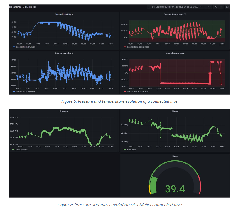
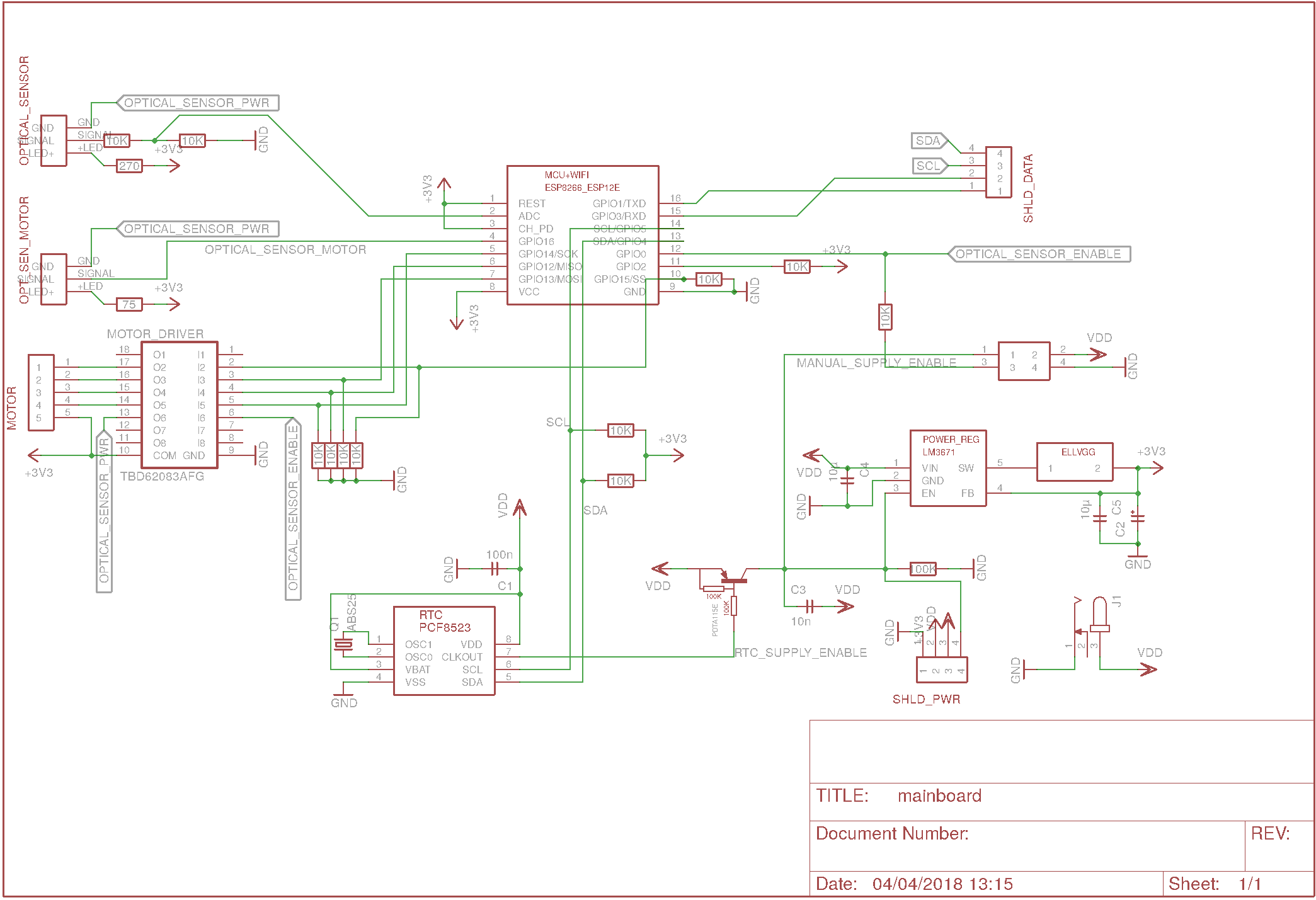
- Data collected by Mellia
The data measured in the hive can then be consulted remotely. Thanks to the Grafana website, which offers a graphical display of data free of charge, the beekeeper can see the evolution of measurements over time.
OpenHiveScale
The Open Hive Scale project is an open-source initiative dedicated to remote hive monitoring. It offers a robust and adaptable mechanical scale, enabling beekeepers to know the weight of hives in real time, in order to monitor the evolution of bee colonies and detect events such as swarming or variations in honey stock. Unlike conventional scales, OpenHiveScale relies on an automatically-adjusted counterweight mechanism, which reduces energy consumption and makes the device more autonomous, while avoiding the drift of sensors commonly used on the market.
Physical Architecture
The physical architecture of the system is based on an aluminum structure, designed to support the beehive (around 40kg in operation), while incorporating a measurement mechanism based on the acquisition of the position of a counterweight. The counterweight is kept in balance by a stepper motor and an infrared sensor, which ensure its return to equilibrium. The principle is based on the Roman balance, a system based on the distribution of loads with support points and a lever, which provides greater precision in measuring the mass of the hive.
Electronic Architecture
The circuit can be broken down into 4 main parts: power supply, microcontroller, optical sensors and motor.
- Power supply :
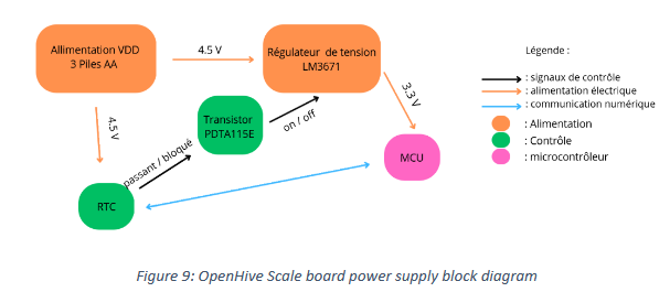
The VDD = 4.5V power source comes from 3 AA batteries in series (3x1.5V). It goes directly into an RTC (Real Time Clock). This component greatly reduces power consumption. It has an internal real-time clock (based on quartz oscillations) that continues to run even when “stopped”. It can be programmed to wake up at any time based on the current time. This signal from CLKout will be used to control the power supply to the rest of the board. This means you can completely cut off the power supply most of the time (only the RTC and its very low power consumption will remain), then reactivate it for a short time only (configurable) in order to take and send the necessary measurements. The rest of the board operates on 3.3V. It's a DC-DC converter (buck down converter) which enables the VDD = 4.5V to be converted to 3.3V. Finally, a clever part of the circuitry links the RTC to the converter. Its base is connected to the RTC_SUPPLY_ENABLE, its emitter to VDD and its collector to the voltage regulator's ENABLE. There are now 2 cases:
When RTC_SUPPLY_ENABLE = 0V (Ground): The base of the PNP transistor becomes negative with respect to its emitter (VDD), it therefore goes into conduction and sends VDD to its collector, the EN (ENABLE) of the LM 3671. The activated regulator powers the rest of the circuit.
When RTC_SUPPLY_ENABLE = VDD: With base and emitter at the same potential, the transistor is blocked. The controller's EN input is then pulled to ground via a 100kΩ pull- down resistor. The regulator is then deactivated.
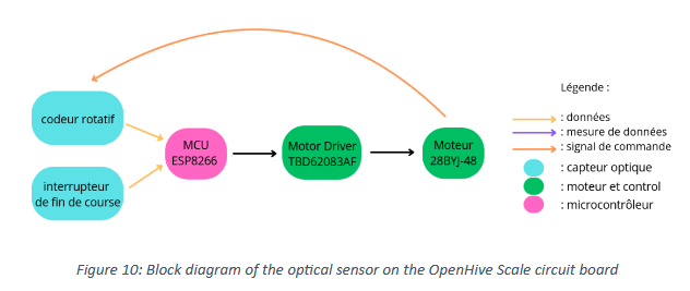
- Optical Sensor :
two optical sensors are used: A platter position sensor (TCST2103, used in endstop): detects the descent of the platter due to a change in weight. There's an infrared LED and a phototransistor, the latter of which has its base controlled by light. So, when a cache passes in front of the LED, the light decreases with the current flowing through the transistor. The MCU (microcontroller) can analyze this decrease and deduce that a weight change has lowered the scale pan. The motor's optical encoder tracks the position of the counterweight. A slotted disk rotates at the same time as the motor. It works in a similar way to the endstop, detecting the passage of a slot in front of an LED.
- Motor :
A 28BYJ-48 stepper motor is used to move the counterweight. It operates with a stator consisting of 4 electromagnetic coils and a rotor with permanent magnets. By energizing the coils in a precise sequence, a magnetic field is created and controlled. The magnets react to this and move, causing the rotor on which they are attached to rotate. The rotor does not rotate continuously, but in small steps (2048 steps to make a complete revolution). This mode of operation makes it possible to be precise and to know at what position it is (and therefore at what weight you are on the scale). Signals are sent by the motor driver for precise control. It can also deliver more current and voltage than if the control signal came directly from the MCU, and conversely it can more easily withstand potential current feedback from the motor, thanks to protective diodes.
Here, it seems to be controlled at 3V instead of the usual 5V, and is therefore likely to be less powerful. Given that the motor doesn't move a lot of weight, this doesn't seem to be a problem.
- Microcontroleur :
The MCU controls the entire board and acts as a link between components. It also incorporates a wifi module, enabling it to be connected directly from a telephone/pc to retrieve data. It analyzes the optical sensors and drives the motor.
- Software architecture
The embedded software architecture manages hive weighing, counterweight balancing and data communication. It is hierarchically organized into several source files that manage these functions. The “openhivescale.ino” file is responsible for transmitting measurements and ensuring compatibility with LoRa TTN. The “scale.ino” file implements the weighing protocol, while “telnet.ino” sets up a remote communications interface. Finally, “wifi.ino” manages the Wi-Fi connection and hotspot mode. The system allows you to set up a Wi-Fi data transmission mode, either by connecting to an existing network, or by creating a hotspot for direct access to the user interface.